North Sea high pressure, high temperature coiled tubing intervention operations
Alan Turner, Bob Murdoch, Halliburton
Within the last 10 years, a number of high-pressure, high-temperature (HPHT) fields have been discovered and brought into production, in the process leading to the extension of existing practices and the development of new technology to enhance reservoir production.
One of these developments has been the application of coiled tubing (CT) as an intervention technique. Operator HPHT CT intervention can be defined as work in wells with over 10,000 psi bottomhole pressure and over 300° F bottomhole temperature (BHT), or wells where the pressure gradient is over 0.8 psi/ft and BHT 300° F. The UK sector of the North Sea has a number of fields that meet this definition.
Coiled tubing (CT) has been used primarily for perforating strategies, e.g., the deployment of underbalance perforating guns during the well construction phase. However, one of the challenging extensions of CT has been on well abandonment and cement squeezing.
Intervention common threads
In the use described above, the operator’s and service company’s preparation for each intervention had the following common threads:
• Each specific case history was produced on a standalone surface installation that had no direct drilling facilities
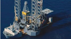
•For HPHT intervention, a suitably rated jackup drilling rig was used as a platform for the services. The rig had sufficient crane capacity to enable lifting of the CT string onboard as well as deck space to hold all associated services
• All well control equipment, such as BOPs, strippers, risers, and production trees, had a 15,000 psi rating
•Other well-related operations that needed to be conducted either concurrently or sequentially around the actual CT intervention had to be allowed for. These included the use of the surface stackups for hydraulic workover (HWO) and slickline intervention
• Size and grade selection of the CT and choice of strips to form the CT string
• Depth-correlation techniques for placing the perforating guns at the desired depth
•The type and number of barriers required, as well as ability of the intervention operations to be flexible in both the sizes of BOP and types of stripper arrangements.
Automatic latchable connector
An automatic latchable connector is used to join two guns together under live-well conditions. The system operates by using standard blowout preventer (BOP) rams, making it well suited for snubbing guns into and out of the wellbore with CT. The connector consists of a stinger assembly that is run with the lower gun, and a skirt assembly that is run with the upper gun. The connector was originally designed to fit within a 4.06-in, 15,000 psi Quad BOP. It uses three of the four ram cavities within the BOP.
Since the introduction of the standard automatic latchable connector, situations have arisen that have caused modifications to this system. Examples of this are connectors for different types and sizes of BOP as well as connectors with shearable subs.
Detachable separating connector
This connector allows the running of long lengths of guns in a single trip using CT or jointed pipe. The company can hang off the guns and the running mechanism returned to surface. Once the company detonates the guns, the separating connector is activated by a small explosive charge, and individual gun sections are detached from each other. The individual gun sections can then be retrieved by the company using a suitable fishing tool that locates in the profile on the lower part of the connector.
Equipment details
The principal components in the system used in the case histories were:
• The CT used on all case histories was 1.75-in. OD, 100,000 psi yield strength internally tapered strings. A similar backup string was available offshore for use during each case history. Each string was approximately 20,000 ft long.
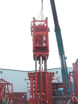
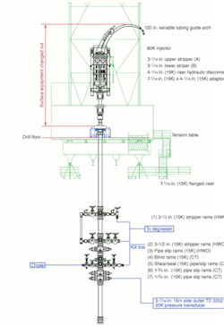
• An 80,000 lb injector was used. Considerations for the selection included the maximum anticipated pickup pull weights of the assemblies and also the modular size of the complete unit.
•The tubing guide arch with a 120-in. variable radius is attached to the top of the injector to properly support, straighten, and align the CT into the gripper chains of the injector.
•A drill-floor located tension table was used in a few of the case histories to support the weight of the riser instead of the weight being taken by the wellhead. The tension-table unit comprises four hydraulic rams that lift (hold) a pancake flange that was located within the riser string, and sized to suit the riser.
•Each used a 15,000-psi quad well-control blowout preventor (BOP) for the rig-up. The type and size was dependant on the individual case history.
• The industry’s standard for CT operations is to use a single active stripper and have a secondary backup stripper. This arrangement was used as a basis for each of the case histories. However, different designs and combinations of stripper have been used. For example, on perforating case history one, a three stripper arrangement was actually used.
• For each case history, multiple runs in hole with different bottomhole assemblies (BHAs) were planned. To minimize the time spent pressure-testing the surface riser connections, a riser quick-connection sub was used. This allowed only the broken connection to be tested each time, instead of the full riser contents.
• Two types of firing heads were used in the three perforating case histories. Both firing heads contain shear pins and are pressure activated. One of these firing heads also includes a vent mechanism, which operates as the guns are activated. The other firing head includes a detonation delay fuse such that the activation pressure can be bled off prior to gun detonation.
• In these case histories, the company used three different sized gun systems: 2 3/4-in.; 2 7/8-in.; and 3 3/8-in. These gun systems also used a combination of Aflas and Viton o-rings for sealing. All the guns systems used 6spf HNS deep penetrating explosive charges. The operator’s choice of gun size depended on the specifications of the individual wellbore.
Cementing case history
This particular operator’s case history involved not only CT intervention but also a hydraulic workover (HWO). The HWO was required for the first stage in the abandonment of the well in that a conduit string complete with two 2.562-in. retrievable plugs was run to the existing production tubing. A common BOP stack was used for both intervention operations. The initial steps in the CT operation were to redress the 7.06-in. BOP with 1.75-in. CT rams. All surface equipment was then pressure tested to 13,200 psi. The coil connector was pressure tested to 10,000 psi.
In total, five successful CT runs were carried out. This began by retrieving both plugs from the conduit string. A combination drift and 16 ppg oil base mud (OBM) conditioning run was made to 16,430 ft. Because cesium formate brine was present in the conduit string, all seals had to be compatible with this and the OBM. An accurate gamma ray/casing collar locator (GR/CCL) correlation run was then conducted. Finally, a cement plug was accurately positioned over the upper set of perforations and successfully pressure tested to 3,000 psi.
For this final run, the coil was run in hole (RIH) to 16,415 ft. A run was performed between 16,415 ft and 16,050 ft to verify the passage through all the deep-set restrictions. Once this run had been completed, the CT was run back down to 16,415 ft. A total of 19.8 bbl of spacer was then pumped at 0.5 bpm while pulling up the CT a total of 565 ft. The CT was then run back down to 16,400 ft pumping spacer at 0.25 bpm at a CT running speed of 15 ft/min. The remaining 4 bbl of spacer was pumped allowing the cement to reach the end of the nozzle.
The 11.4-bbl cement plug was then circulated into the CT and pumped around until 0.3 bbl had circulated up around the end of the CT. Prior to pulling up the CT the top of cement (TOC) was approximately 20 ft above the nozzle. An additional 11.1 bbl of spacer was pumped while pulling back with the CT. The pulling speed and pump rate of the cement was controlled so that the TOC stayed above the nozzle as the CT was pulled up through the wellbore. After the 11.4 bbl of cement had been pumped, both TOC and nozzle were at 15,850 ft. The nozzle had been picked up 550 ft and 11.4 bbl of cement had been displaced. At this point, pumping was stopped while the CT was pulled back to 15,650 ft.
The surface rig up was changed to enable the pumping of 19.23-ppg OBM, which was being held in the reserve pits. This OBM was then circulated, first to displace the 5 bbls of tail spacer, then to displace the tubing contents to the OBM.
After 19.23-ppg OBM had reached the nozzle, the tubing was pulled out of the hole at 40 ft/min while the OBM was being pumped at 1 bpm. When pulling back up into the conduit string the pull-up rate was reduced to 10 ft/min.
The cement plug was left to set for approximately 36 hours, after which the cement plug was successfully pressure tested.
The total time taken for this case history was 170 hours. Of this time less than 8 hrs was actually classified as nonproductive. The majority of this was related to pressure testing of surface equipment.
Perforating case history
On completion of the rig up, the first stage of this intervention was comprised of a combined clean out/logging and circulation run. The operations during this run went smoothly with no NPT recorded. However, due to bridging across the production liner, the washing BHA could not wash down to TD. After several passes with little headway, a circulation sub was opened and the well was displaced to brine.
After inspecting the first BHA at surface and replacing with the rotating jetting tool, the assembly was again RIH. Once on bottom the BHA again tagged higher than expected. The CT was picked up and jetting operations commenced once more. The CT was then RIH while simultaneously jetting, and on this occasion tagged at a lower depth. This method was again repeated several times with the BHA finally tagging at its expected depth of 20,560 ft. After this tag was confirmed the CT was then POOH.
As the majority of HPHT wells are produced from small production facilities, the goal exists to conduct CT interventions without the need for a jackup installation. There have been feasibility studies conducted over the past two years detailing specific field and well needs. There has also been limited CT intervention conducted to clean a safety valve on at least one field. This is an area of investigation that will continue over the next few years.•
Editors Note: This paper is a summary of SPE 93956 presented at the 2005 SPE/ICoTA Coiled Tubing Conference and Exhibition held in The Woodlands, Texas on April 12-13, 2005.
