PRODUCTION TECHNOLOGY: High methanol recovery rate reduces cost, handling on Canyon Express
A cost-effective system to help ensure the flow of deepwater production across extended distances has been developed by Paragon Engineering Services of Houston. The application of this system is making the newly announced Williams Canyon Station project in the Gulf of Mexico viable while helping to advance the industry's deepwater development capability.
Using a distillation process, Paragon has produced a system for the effective recovery and reuse of methanol as a hydrate inhibitor. Depending on the operating conditions, Williams is expected to recover about 75-90% of the chemical for re-injection using Paragon's design application.
The methanol regeneration process is expected to bring an estimated cost savings of $60,000/day while successfully producing the 500 MMcf/d of gas from deepwater subsea wells. The saving makes the project economically viable. The subsea wells are located in up to 7,200 ft water depth, representing the Gulf's deepest subsea development to date. Production is expected onstream by summer 2002.
Operators have used nominal amounts of methanol for many years to inhibit the formation of hydrates, which can block production flow in piping. However, its use on the Williams project represents an expanded application in terms of volume and importance to a deepwater project: The landmark project calls for the effective storage, regeneration, and distribution of 1,900 b/d - or about 55 gallons/minute - of methanol.
Project scope
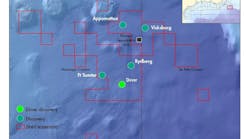
Newbuild facilities for Canyon Station call for a shallow-water platform destined for Main Pass Block 261JP in 299 ft water depth to accept deepwater production from nine subsea wells in three fields: Aconcagua, Camden Hills, and Kings Peak. The subsea wells are located 55 miles south of Williams' proposed facility. A 110-mile closed loop 12 3/4-in. diameter pipeline will gather production from the wells to the Williams Canyon Station host platform.
The owners of the three fields - TotalFinaElf E&P U.S.A., Marathon Oil Company, BP, Pioneer Natural Resources U.S.A., and Mariner Energy, - are working on a project known as Canyon Express to develop a gas-gathering system and infrastructure, which will tie back the deepwater wells to the Williams Canyon Station host platform. The Canyon Express gathering system will serve the three deepwater fields:
- Camden Hills: Operated by Marathon, in 7,200 ft water depth, includes two wells. Shareholders include the operator with 50.03%, Pioneer Natural Resources USA (33.3%), and TotalFinaElf (16.67%)
- Aconcagua: Operated by TotalFinaElf, in 7,000 ft water depth, includes four wells. Shareholders include the operator with 50%, Mariner Energy (25%), and Pioneer Natural Resources USA (25%).
- Kings Peak: Operated by BP, in 6,200-6,400 ft water depth, has four or five wells. BP is a 100% shareholder.
Technical challenges
As part of the development strategy, Paragon is performing project management, engineering, design/drafting, procurement, and fabrication inspection for the new platform. Tie back of the subsea wells to the host platform presents technical challenges, as hydrates could plug the line at any point.
Equally significant is the 7,200-ft water depth, where temperatures below 40 degrees F can cause hydrates to form at the wellhead and in the pipeline. Recovered methanol plus make-up - due to losses in the gas and hydrocarbon liquid phases - is injected into each of the wells to effectively inhibit the formation of hydrates and ensure gas flow throughout the entire system.
The first step of the process on the Canyon Station platform involves separating the liquids from the gas through two, 50% high-pressure separators. The condensate/water/methanol mixture is then separated into hydrocarbon and water phases in a three-phase low-pressure separator.
The water phase, which contains the bulk of the methanol, is further processed to reduce the hydrocarbon concentration from approximately 1,200 ppm to less than 20 ppm. This low hydrocarbon concentration is achieved with high-efficiency condensate coalescers. A de-sanding hydrocyclone and a degassing vessel are installed upstream of the coalescers to ensure their proper operation.
The methanol/water mixture is then processed in the methanol regeneration system consisting of methanol/water preheaters and a distillation column with a re-boiler, total condenser, and reflux pumps. The methanol/water preheaters heat the methanol using the hot water distillation bottoms product. The methanol recovery process will have a design capacity of the 2,750 b/d of inlet fluids: 1,500 b/d of methanol and 1,250 b/d of water. Upon regeneration, the methanol is 95% pure.
Operational flexibility
The methanol regeneration system is designed with operational flexibility in mind. First, multiple feed points are provided on the distillation column such that the feed location is optimized as the feed properties change throughout the life of the field. Also, an automated recycle loop, which feeds distillation bottoms product back to the distillation column through a recycle cooler, allows the methanol regeneration system to stay online during operating conditions when no feed is coming from the main process.
Several steps were taken to mitigate corrosion and scale problems in the methanol regeneration system due to the potentially high dissolved solids content of the produced water and the presence of methanol. The methanol/water preheater plate pack is titanium construction. The distillation column trays and valves and the re-boiler tubes are stainless steel construction.
Both the distillation column and the re-boiler have a special internal coating that will stand up to the high temperatures and the corrosive nature of the liquid. The re-boiler design also includes provisions for cleaning the tubes in place. Another design consideration for the methanol regeneration system is for the removal of hydrocarbons that may accumulate in the distillation column and decrease the methanol regenerating capacity due to increased vapor and liquid flow.
First, a skim connection and interface level gauge are installed in the bottom of the column to remove any heavy hydrocarbons that may collect. Second, a total liquid draw tray is included in the column such that a three-phase separator may be installed at a future date if accumulation of mid-range hydrocarbons in the column does occur.
Schedule
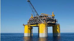
The Williams Canyon Station design calls for a four-pile, four-legged production platform destined for Main Pass Block 261. The topsides production deck is estimated to weigh 3,500 tons.
The jacket is scheduled for installation this summer (2001), with the deck to follow in the spring of 2002. Following jacket installation, Canyon Express will begin installation and testing of the umbilical to ensure its operability. To facilitate the fasttrack process, Williams requires a concurrent facilities design-and-build effort. Paragon is designing the deck using the 3-D Plant Design Management System (PDMS) to facilitate early resolution of design clashes and to improve operability and safety through better anticipation of hazards.
The engineering effort includes topsides system design for compression and separation facilities, water treatment, instrumentation and utilities, including termination and connection of the power and control systems from the umbilical bundle to the master control station for the subsea wells.
Author
W. Hickman Brown is a project manager with Paragon Engineering Services. He has more than 25 years of experience in the design/engineering of offshore facilities and pipeline systems, much of it with Mobil, Superior, and Shell. He holds a BSME from New Mexico State University and a MS in Ocean Engineering from the University of Rhode Island.


