Karim Jan, Simon Luffrum, John Shield, Paul Brett - Subsea Riser Products
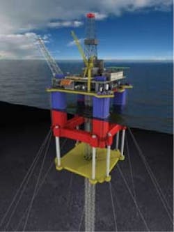
As the development of offshore hydrocarbon reserves extends into greater water and well depths, riser system design and supply becomes a critical industry challenge. One such example is the drilling of pre-salt wells in water depths approaching 3,000 m (10,000 ft). This is a complex undertaking, and can require extensive initial well construction work as well as regular intervention throughout production life. For these reasons, and considering recent day rates for a mobile offshore drilling unit, operators are considering drilling these wells using a dry tree floating production system with surface BOP.
Drilling risers in these surface BOP systems must contain internal pressures up to 15,000 psi (such as in the Gulf of Mexico’s Lower Tertiary play), resulting in the need for a large wall thickness and high-grade materials to resist burst. Adding to this technical challenge are the difficulties of sour service.
One solution is a technique of fabrication using shrink fitting which allows higher grade materials to be used and eliminates the problems associated with welding thick walled pipes.
For many years shrink-fitting has been one standard connection method. A shaft is inserted into a pre-heated component then left to cool. Although common in many industries, its use in the offshore oil and gas industry is limited. Welding and threading are the connection methods of choice. This article describes the development, testing, and manufacture of a full-bore (19 ¼-in. or 49-cm inside diameter) shrink-fit riser connection for a high-pressure drilling system with a surface BOP. It also describes the methods used and the value gained using such a system. It will discuss the applicability of the system already constructed for a North Sea application to deepwater systems in which high strength steels of 110 ksi and beyond might be employed.
Design considerations
The shrink-fit connection and riser system was developed in response to the challenge of making a cost efficient shallow water (130 m or 427 ft MWD), sour, high pressure subsea tieback. A key to this challenge was the maximum predicted shut-in tubing head pressure of approximately 11,000 psi. Ultra high pressure wells typically are drilled using a subsea BOP, low pressure marine drilling riser, and semisubmersible rig. However, in this instance a jackup drilling rig was selected with a strong preference to maintain a full bore riser with surface BOP.
This arrangement allowed cost benefits on the rig rates but placed challenges on the riser system.
The preliminary design and analysis of the riser system indicated that a solution could be achieved with a 19 ½ in. (49.53 cm) bore riser with a 2 in. (5.08 cm) wall thickness using a relatively high strength steel (80 ksi). It was recognized that manufacturing such pipe and fabricating riser joints would be a challenge if NACE requirements were to be achieved. Given the commercial and schedule risk, the option to use a new shrink fit method was considered, and ultimately qualified and selected in preference to welding.
The maximum well shut-in tubing head pressure was predicted to be 11,000 psi; but because of uncertainty about the exact pressure, the maximum design pressure of the riser was taken to be 12,200 psi (approximately 10% margin). As well as designing for burst, this internal pressure results in large tensile end cap forces (15,800 kN), dwarfing the external tensioner capacity of 2,670 kN.
Even considering high strength steel, the resulting wall thickness is very large and this results in a very heavy riser with high bending stiffness. Although the water depth is relatively shallow, the combination of limited tension capacity of the rig, the large riser diameter, and high currents result in high bending loads, particularly near the riser end constraints at the seabed and vessel interface.
The maximum riser weight that a standard jackup can deploy is around 170 metric tons, generally limited by the riser tensioner system capacity. Using higher strength steel (>80 ksi) to reduce weight was not practical for this project due to qualified pipe availability constraints and weldability concerns.
The riser screening analysis suggested that 19 ¼-in. ID, 2-in. WT, 80-ksi steel would be suitable pipe section to withstand the predicted load; and the total riser weight would be within a nominal jackup rig’s capacity. Subsea Riser Products (SRP) selected a low-carbon, high-strength steel (modified ASTM A182 Grade F22, 80 ksi, improved weldability) which is readily available (though only as a forged product in this diameter and wall thickness) and has excellent resistance to fatigue (fracture toughness) and sour gas (hardness).
In this application, applied loads are the main design driver in coupling selection rather than speed of make-up or compact size as in other riser systems. However, both these requirements have practical limits and are factors to be considered.
Owing to the high tension and bending loads on the connection, SRP elected to use a custom designed compact bolted flange. With detailed finite element (FE) analysis, SRP developed flange face profiles and preload values specifically for the extreme load cases as defined by the global riser analysis. This resulted in a compact flange with 12 bolts which is more efficient than a comparable API flange (18 ¾-in. 15 ksi) in terms of drill floor make-up time. Coupled with a 100% bolt tensioning system, the make-up time is comparable or better than low pressure “fast make-up” riser connections. Hence the basis of the riser system design was defined and only the method of construction/fabrication needed to be finalized.
Riser joint construction
Because of the pipe material, diameter, and wall thickness, the scope of supply was beyond the capacity of candidate pipe mills to make a reasonable length standard riser joint. This meant that relatively expensive forged and machined pipe was the only solution.
Welded construction is the standard method of joint construction, so the riser material was modified to maximize weldability. Welding companies were approached to do feasibility studies on welding these components in accordance with the project requirements.
All the studies determined that welding could be feasible, though it presented technical challenges and would require development and qualification to achieve a level of commercial confidence. Consequently, when combined with schedule pressure this method of construction was eliminated.
Other methods of connection (such as threading and friction welding) were considered and eventually discounted either because of the technical challenges of joining such large components, or because their performance in riser loading conditions was unknown and could not be determined in the short development time frame.
The option of shrink-fitting was considered, even though it was new and unproven. In shrink-fitting, an oversized shaft is inserted into the female component (e.g. hub) which has been expanded with heat. The components are allowed to cool and the resulting interference fit offers a structural connection. This has been used for years on rail wheels, gears, etc. In addition to the structural connection, shrink fit also offers a seal due to the high levels of preload that are achieved.
2H Offshore and Subsea Riser Products previously developed a shrink-fit design for flange to pipe connection. The status of the development work, the simplicity of the process, and the predictability of the assembly behavior enabled development of a high integrity shrink-fit connection to meet the project requirements within the project schedule.
Development
Since a shrink-fit connection loaded in tension is primarily a friction joint, the total tensile capacity of the connection depends on the surface area, coefficient of friction, and contact pressure between the two components. SRP, together with 2H Offshore, developed a testing program and suite of calculation tools to complete a screening analysis of the geometry combinations (external and internal diameters) and mechanical properties (Poisson’s ratio, modulus of elasticity) of the mating components. This also was used to input variables derived from experimental data (such as friction factor) into the detailed analysis.
One of the analysis tools developed was a method of accurately predicting of the contact pressure generated between the two components by hand calculation. Based on simple thick walled theory, it allows quick and easy assessment of the shrink fit assembly under a range of design and operating conditions.
Results from calculations compared favorably to finite element analysis and strain measurements. This design tool was fundamental to develop the final connection profile as the external constraints on design were refined throughout the project. Such constraints included practical limits on forging sizes, rotary table drift, and minimum assembly clearance.
Two testing programs were undertaken as part of the shrink-fit development.
Small-scale testing
A small-scale test program with simple geometry was used to verify the shrink-fit analysis methods and to determine the effect of surface finish on sealing and pull-out resistance. It was also used to assess the pull-out resistance of mechanical details designed to supplement the friction joint.
The small scale tests were conducted using 3-in. (7.62-cm) diameter shafts fitted into capped cylindrical housings. Pressure then was applied within the housing to test sealing and an external jack applied load.
This testing proved the predictable behavior of the seal and friction joint with various surface finishes, validating the contact pressure calculations and providing accurate friction factors for further development work and final prototype design.
Medium-scale testing
With prototype design complete, 2H Offshore and SRP developed a half-scale testing program designed to reflect the behavior of the full-scale flange while enabling the use of readily available materials and jacking equipment.
The purpose of the test program was to validate the design methodology of the more complex connection, prove the connection seal and strength integrity, and assess the practicality of full-scale assembly.
Four half-scale test pieces were assembled and tested in the program -- two prototype pieces and two pieces designed to test the behavior and capacity of the individual design features: the friction joint and mechanical locking. All were made from steel representative of the final riser joint material.
The strength and sealing capacity of the shrink-fit connections were tested with various combinations of pressure, bending and tension, including:
- Hydrotesting to 13,500 psi
- Gas testing to 12,200 psi
- Hydrotesting to 12,200 psi with external loads up to 450 metric tons (496 tons)
- Hydrotesting to 5,000 psi with external loads up to 1,050 metric tons (1,157 tons)
- Bending and tension loads representing greater than 50-year storm event in service.
Taking the test scale into account, the program achieved test conditions more than twice as onerous as those predicted for the in-service units. The test showed that capacities of the friction joint and mechanical locking features are additive and exceed the pipe capacity. It also showed that the shrink-fit seal was resistant to variations in pressure and external load, even severe overload conditions that exceeded the friction joint capacity.
Fatigue
A primary consideration in riser design is resistance to fatigue. Riser fatigue is driven by growth of cracks due to cyclic axial stress, primarily due to varying bending. This is assessed by a global riser analysis which includes the cumulative fatigue damage from first order fatigue and vortex induced vibration (VIV) effects under a service life environment. From this analysis, a fatigue life for straight pipe is predicted which can be reduced in a nonlinear manner by stress concentrations, or “hotspots,” that locally amplify axial stress ranges. These hotspots can occur at the transitions from pipe to flange, and tend to be driven by flange geometry. An example of this is the use of integrally forged joints with elliptical taper sections to smooth transitions.
Mismatched weld fit-up causes stress concentrations, so eliminating the pipe to flange weld automatically can improve the fatigue performance of the riser joints.
The shrink-fit flange-to-pipe connection was evaluated for stress concentrations using finite element analysis. The tapered relief sections designed by Subsea Riser Products resulted in an axial stress concentration factor (SCF) which is better than the pipe. While there is increased axial stress at the pipe-flange transition, the axial stress ranges due to varying bending actually are reduced, resulting in a SCF less than unity and a fatigue class of parent material B1.
Shrink-fit assemblies also experience a different type of fatigue failure – fretting fatigue, which is driven by cracks initiated at the mating surface by the rubbing of the shrink-fit surfaces. Fatigue tests conducted by Subsea Riser Products with project material demonstrated that under contact pressures experienced in the shrink fit, material under fretting and varying axial stress still outperforms B1 class fatigue curves. This means no design considerations must be made for this effect.
In conclusion, extensive global riser analyses, combined with exhaustive FE analysis and testing, yield a fatigue life which exceeds the requirements for the project.
Flanged connection design
The flange-to-flange bolted connection is achieved with 12 preloaded 110 ksi 3-½-in. (8.89-cm) studs and sealing is achieved with an AX-type bore seal gasket. Subsea Riser Products developed a custom tapered flange face to cope with extreme 50-year environmental loads, 12,200 psi internal riser pressure, and high thermal stresses caused by expected 121 °C (250 °F) mud return temperature. A principal reason for FE analysis is to combine the residual stresses introduced by the shrink-fit technique with the service loads and thermal stresses from internal fluids.
The flanged connection was analyzed against project specific loads in each API-RP- 2RD rating category (normal, test, extreme, survival) along with 20 more load cases. The performance was assessed for von Mises stress, SCF values, bolt stresses, flange face separation, and gasket sealing pressures.
Limits placed on these criteria enabled development of a capacity chart for the connection. The efficient design of the flange face resulted in the capacity envelopes being governed primarily by von Mises stress near the pipe/flange transition.
Production
Shrink-fit assembly relies on the ability to control the geometry and alignment of the two components. The assembly clearance is affected by machining tolerances, temperature control (thermal expansion), and the relative position and angle of the components.
SRP constructed an assembly jig to get precise control of the angle and position of the joints in both the cold and hot states; as the flange is heated on the jig.
Heating is by induction coils and temperature is monitored in four locations to ensure uniform heating and expansion. Pipe and flange diameter and ovality matching is not necessary. Fatigue issues with weld alignment are avoided in this design which increases the flexibility of the production schedule, as a just-in-time machining can be employed.
Once insulated and prepared for heating, there is no need to interfere with the hot flange, so assembly hazards are controlled.
As the flange cools, it grips the pipe and the connection is completed. The process takes approximately 15 hours – limited by the power output of the induction heating unit and cooling time of the assembly; both of which can be accelerated. Once cool, the assembly is checked for dimensions before the joint is sent for final machining, hydrotesting, and coating.
Future developments
The excellent fatigue performance of the shrink-fit connection lends itself well to riser joints, bend stiffeners, and other fatigue critical services. SRP is developing a low-profile shrink-fit sleeve to construct joints up to 30 m (98 ft) long for deepwater drilling. Extensive FE analysis of a sleeve design already has been done, and the results show that a sleeve coupling with a wall thickness comparable to the pipe would be feasible. In deepwater applications high strength steels of 125 ksi minimum yield strength or greater may be used with the shrink-fit technique to minimize riser weight. In critical locations along the riser, forged taper joints often are required to control bending and fatigue. The use of shrink-fit flanges or connections allows equivalent fatigue performance to be achieved using “fabricated” joints. This simplifies the procurement process to reduce cost and shorten the schedule.
Another interest is the possibility of shrink fitting a steel flange onto a titanium pipe. This allows the designer to take benefit from the titanium properties without the cost and complexity of the titanium connector that must either be forged integrally or connected through a welding process that degrades the fatigue performance.
Summary and conclusions
SRP has shown that it is possible to use thermal shrink-fitting to assemble riser joints for HP/HT applications in diameters for which threaded connections have not yet been developed or proven, and where welding is not practical or commercially feasible. This allows high and ultra high-strength steel riser joints to be fabricated with lower riser weights, which is critical at deeper water depths. Additionally, ongoing development has proven the technology for titanium alloys and for steel/titanium alloys.
Editor’s note
This updated article was originally presented at the Deep Offshore Technology (DOT) conference in Monaco, in November 2009.
References
Qualification of Heavy Wall High Strength Steel Riser Connectors for Dry Tree HPHT
Det Norske Veritas, “Fatigue Design of Offshore Steel Structures” DNV-RP-C203, August 2005.
API – “Design of Risers for Floating Production Systems and Tension Leg Platforms”. API-RP-2RD, 1st Ed., June 1998.


