Escravos float-over installation dictates platform design
Kevin Simmons, Bryan Duhaney - Chevron Nigeria Ltd.
Chevron Corp. subsidiary, Chevron Nigeria Ltd. (CNL), has completed a float-over installation of the Meji Gas Gathering and Compression Platform (GGCP) on the Escravos Gas project Phase 3, marking the first of its kind for the company in the region.
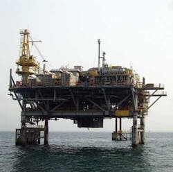
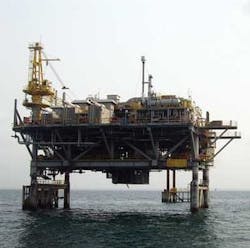
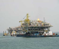
Meji GGCP after installation, offshore Escravos, Nigeria.
Float-over installation of topsides is a proven, but infrequently used method. However, it is being used more now due to the scarce availability of heavy-lift crane vessels for work in shallow waters, and the cost and schedule advantages of installing pre-commissioned, integrated, single-piece topsides. Also, the desire to reduce increasingly expensive offshore hook-up and commissioning time has helped usher in this era of high demand for float-over installation.
Concept selection
In a float over the topside module typically is placed on a barge or heavy transport vessel positioned within or around the legs of a pre-installed substructure. The module then is settled onto the jacket legs by a combination of vessel ballasting and a mechanical lowering system. The operation of incrementally transferring the module loads from the barge to the substructure is particularly to environmental loading, so innovative and nontraditional approaches to the topsides and substructure design are necessary.
A float over requires increased interaction between the installation vessel and the jacket or substructure. It also requires a greater degree of vessel positioning compared to traditional topsides-to-jacket lifts.
Planning for the float-over installation of GGCP began in 2001 during concept selection of the Meji field development. Kvaerner Enercon carried out preliminary design of the central hub production platform. Hyundai Heavy Industries secured the EPCI contract.
Escravos Gas Project Phase 3 required a design that could allow future field development through expansion of existing gas gathering and compression facilities by adding capacity. The simplified hub solution required the fabrication and installation of a single Meji GGCP topside bridge connected to an existing facility. The size and tonnage of the GGCP were larger than the other field facilities and well beyond the lift capacity of any vessel that traditionally operated in the area.
The platform would be installed in very shallow water (8 m [26 ft]) among an extensive network of operational pipelines, which further restricted access by a majority of the available heavy-lift fleet. Installation contractors bidding were free to propose any method of installation to best counter the existing challenges and to minimize offshore installation, hookup, and commissioning time in the security sensitive region.
The best installation solution from a technical and cost perspective was found to be the float-over method.
To meet the aggressive development schedule while leveraging as much local content as possible, close coordination with design and fabrication subcontractors, Cakassa Engineering and Nigerdock (Nigeria), as well as early procurement and delivery, were identified as critical.
Metocean criteria
Many of the offshore industry’s design practices stem from typical Gulf of Mexico developments, which use 100-year storm events with significant levels of energy generating wave periods of 13 to 16 seconds. The West Africa scenario is much different. The storms tend to be milder with more intense squalls in the north than in the south. Normal wave conditions tend to be multi-peaked and characterized by a bi-modal spectrum. As a result, the wave events tend to have long periods and are extremely directional.
Currents in the region are more complicated than waves and winds, and there are limited design references to account for them or to understand them adequately.
Most West Africa shallow water lifts are governed by metocean limits of wave height, and the lift vessel response to period swells. For a float over, the designer also may need to consider current direction, swell direction, and tidal range variations depending on their severity.
While the West Africa weather extremes generally are not as severe as in the Gulf of Mexico, the float-over method can be more vulnerable to environmental factors in West Africa than would be a similar lift in the GoM. This was the case for the EGP3A.
Monthly metocean criteria were analyzed for the target installation period of October to May.
Additionally, tidal movement in shallow water was studied to ensure there would be sufficient clearance for entry of the loaded float-over vessel, as well as for the exit after offloading the topsides.
Environmental criteria
The environmental criteria were based on site-specific data from Fugro GEOS, as well as company proprietary historical data. The data revealed swell and wind waves in the Escravos region were multi-peaked and distributed with different relative spectra, which added an element of design complexity. These environmental conditions combined with the jacket–barge configuration and orientation would influence the barge motions. MOSES software determined the magnitude and direction of the motion induced loads.
From this analysis the designers discovered the governing design load case for the substructure would occur during the float over. It would be caused by loads induced by environmental factors on the loaded float over barge.
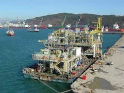
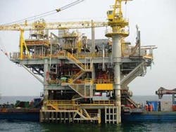
Meji GGCP topsides (rear module) after load-out from HHI’s yard in Ulsan, South Korea. Fabrication and assembly of the two topsides was done at this yard.
The combined sea state, specifically direction, was an important factor in the analysis as the dominating swell from the south-southwest had a significant impact on the float over operation and, hence, the jacket design.
It was determined that the installation could occur approximately 80% of the time during the months of January and February. The percentage decreases over the subsequent months such that the optimal installation window was November to March.
Meanwhile, the platform coordinates were established during FEED based mostly on non-installation factors such as pipeline routes and location of existing facilities.
Transportation, installation
Many of the large offshore facilities are fabricated in the Far East as they generally have the rolling mills, labor, and equipment at competitive rates to support such projects. However, this region of the world is very remote from West Africa, and the project was challenged to account for transit time and the impacts of weather and transportation damage in the design and schedule.
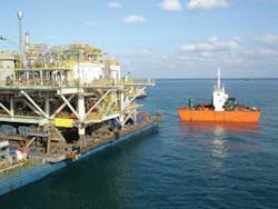
Float-over bargeHD-1007 during float-on operation to MV Swift.
To solve the problem of speedy transport, but still allow for installation in shallow water, the EGP3A team applied a ‘piggy back’ transport approach, which required two additional operations beyond typical topside load out and required additional engineering study, design, and planning.
The GGCP topsides were first loaded on to the float-over barge by skidding, and then sea fastened. The entire barge and topsides were then floated on to the Dockwise heavy-lift vesselMighty Swift in Ulsan, Korea. The vessel then was de-ballasted, sea fastening of the float-over barge to the dry-tow vessel was completed, and GGCP was transported to Malabo, Equatorial Guinea. There, the float-over barge was floated off in a reverse process and towed by traditional tug to the installation site.
Float-over sequence
Limited lift capacity associated with shallow water derrick barges reduced the opportunity to use a single integrated deck lift installation. Therefore, float over was used to install the Meji GGCP topside.
Preparation and initial positioning. The developed Meji field has existing pipelines and platforms near the installation site. Therefore, the final mooring design used a combination of lines attached to existing structures to avoid anchor placement in a condensed pipeline region. Two primary structures, an existing jacket and the recently installed Meji GGCP jacket, were used as anchor points to guide the barge into place, while three mooring lines provided the resisting tension on the barge’s stern to prevent sway during initial approach.
GGCP topsides on boardHD-1007 en route to the jacket.
Positioning and final docking. Typically, float over relies on traditional ballasting techniques to transfer load from the barge to the jacket’s legs. However, the Meji installation site, with relatively shallow water depth, required an additional measure to ensure vertical clearance between the deck and jacket legs upon entrance. The design team used a hydraulic jacking system to achieve the required vertical clearance.
The design required a jacking system that could lift the deck approximately 2.2 m (7.2 ft) above the transport condition for entry. This height was based on the worst-case environmental condition expected during the operation. Another requirement was the rate of jack lift and retraction due to the load transfer criteria established during detail design. The combined criteria resulted in the selection of eight hydraulic jacks that would set the deck in its final position.
The installation barge was outfitted with appurtenances including sway and surge fenders, specific for the float-over operation. The combined fendering system was designed to ease the transition through the jacket with sufficient clearances, which reduced the sway impact loading upon docking. The surge fenders were installed to lock the barge in its final docking position.
Ballasting and load transfer. The surge and sway fenders were engaged during final docking, which reduced horizontal impact loading from barge motions and provided a stable environment for ballasting and load transfer to begin. Vertical impact forces were reduced by elastomer-based leg mating units (LMU) designed to support 50% of the deck load during load transfer.
Achieving the design draft in a designated time was another critical factor. Ballasting traditionally has been the primary load transfer mechanisms for deeper water float-over installations. The project team used project-specific ballasting rates to perform the load transfer in the available 12-hour tidal sequence. The existing barge ballasting system was upgraded to achieve the designed rates.
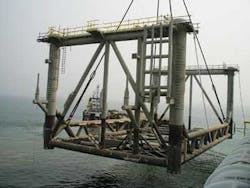
Installation of the GGCP 500-metric ton (551-ton), four-pile inverted table jacket. Fabrication and assembly of the GGCP substructures and bridges were done at Nigerdock’s Snake Island facility in Lagos, Nigeria.
The barge was ballasted initially to a design draft that reduced the deck to jacket gap without steel-to-steel contact, while the jacks maintained the designed stroke of 2 m (6.6 ft). The vertical clearances among other critical barge motions were monitored to ensure the overall barge movement was within designed tolerances and that the deck legs were aligned with jacket legs during load transfer.
Initial load transfer was increased incrementally to 50% when the hydraulic jacks were lowered and steel-to-steel contact was initiated between the jacket and deck legs. Simultaneously, the barge was ballasted to ensure stability was maintained during load transfer. The 50% load transfer was maintained as per design, while the barge was ballasted and jacks were extended. This ensured the barge would have clearance for removal.
The design draft condition was maintained for barge removal and provided enough stability to remove the jacks fully without barge heave motion. Clearances were re-evaluated and the barge removed by pulling on the three stern anchors.
Jacket design
The float-over conceptual design originated during the FEED phase with a non-traditional inverted table jacket. The concept was chosen to facilitate easy barge docking and undocking during the installation. Based on barge availability and traditional barge sizes, the proposed jacket width would accommodate a small- to medium-size barge. A detailed study evaluated barges that were able to transport the deck with its estimated payload of 2,000 metric tons (2,205 tons). This design component continued during detailed engineering resulting in the selection of theHD-1007.
The rectangular jacket orientation balanced the facility’s operational requirements and the barge’s geometrical constraints to perform the float over. Based on the barge’s overall length, width, and depth, minimum vertical and lateral clearances were established to facilitate docking. These requirements provided a basis for the jacket design. Traditionally, equipment layouts and operational requirements govern the platform design. However, the installation method was critical to the platform geometrical configuration and structural layout.
The field’s water depth also influenced the jacket design. The shallow water combined with the barge’s vertical clearances limited use of traditional methods common for deeper water to stiffen the structure. This resulted in a structure with limited stiffness in the perpendicular direction to the barge. Despite the limitation, barge motions during docking were prominent in this direction.
Multiple ways were identified to increase the structure’s stiffness such as increasing the leg’s wall thickness or designing a small truss-type structure to absorb the load. A study indicated the most economical solution was a truss structure to span the lateral direction to provide the additional strength to support the impact loading from the barge during docking, load transfer, and undocking. The truss structure was designed with sufficient clearance for the barge during the docking phase and was a critical link for overall jacket strength.
Deck mating simulation. The deck mating analysis was based on extreme force load cases for the structural design of the jacket and topsides. MOSES was used to simulate the barge’s motion characteristics and to identify the loading on the jacket using a time domain analysis. Multiple load cases were identified from the docking, load transfer, and undocking stage to represent the float-over method.
The docking stage required a minimum clearance of 1.0 m (3.28 ft) between the stabbing cones and jacket guiding cones, considering all barge motions. The height was maintained by the ballasting conditions and jack stroke of 2.2 m (7.2 ft). The sway fenders were tapered at two stages to facilitate the barge entry with a clearance reduction from 0.2 to 0.05 m (8 to 2 in.). Three primary cases were developed to represent docking. Each case varied the barge steps into the jacket resulting in high impact loads from the fendering system.
The load transfer stage was an incremental approach to transfer the load from the barge to jacket upon final docking. Three cases simulated the load transfer at 0%, 25%, and 50%. Results showed that the 50% load transfer stage provided a relatively high load application from the deck leg to the top of the jacket. Leg mating units were designed to absorb the vertical load, but could not withstand the high horizontal impact loads identified from the analysis. Therefore, the entire load was absorbed by the horizontal stiffness of the jacket and governed the jacket design.
Undocking was similar to docking except for the reduction in mass from the barge as the deck was removed. In addition, the draft was changed to facilitate the barge removal.
Acknowledgments
The authors acknowledge the operator, Chevron Nigeria Ltd., its joint venture partner Nigerian National Petroleum Corp., and Hyundai Heavy Industries for permission to publish this paper at Offshore West Africa 2008 in Abuja, Nigeria. The contributions of the Kvaerner Enercon design team, the Hyundai Heavy Industries design team, the Hyundai Heavy Industries project management and installation teams, and various other design and fabrication contractor teams also are acknowledged.
Editor’s Note: This is an edited version of the paper presented by Kevin Simmons at PennWell’s 2008 Offshore West Africa Conference & Exhibition in Abuja, Nigeria.
