Design, reliability issues impact mooring chain, connector selection
Jonathan Fernandez, Vicinay Cadenas
Chain is widely used in mooring applications for offshore floating structures, usually as part of a system combining chain and rope, be it fiber or wire. Chain is favored for mooring systems for several reasons:
- It is rugged and less prone to damage than wire or fiber rope when used with topsides, catenary, or seabed equipment. It is also easy to handle and requires only standard topsides tensioning equipment
- It is less prone to corrosion than wire rope
- Chain weight per unit length is higher than wire rope for a given strength. So chain can be used mid-line as a clump weight to alter the catenary shape or as a ground line so that a smaller anchoring system can be used.
Types of chain
The chain used in offshore applications is one of two main types, studless or studded. Selection is generally determined by the application. Studlink chain is commonly used in temporary moorings, while studless chain is usually selected for permanent installations.
The size of offshore chain varies greatly, from 70 mm (2.8 in.) up to the largest ever manufactured at 182 mm (7.2 in.) in material diameter, weighing around 500 kg (1,102.3 lb) per link. Offshore chain today is also produced in various grades, typically R3, R4, and R5.
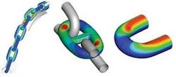
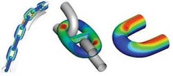
Stress contour plots: Left - chain on bending shoe, Center - chain torsion, Right - chain out-of-plane bending fatigue.
Chain is selected to meet certain strength and fatigue requirements, using mooring analysis tools and classification society standards. Normally, chains are designed as if they will be working under straight tension. Sometimes, however, the chain’s structural integrity needs to be assessed under special operating conditions, which can be more demanding.
For example, chains and other components can be analyzed in detail when operated with topsides hardware such as fairleads, bending shoes, chain stoppers, and trumpets or when subjected to other forces, including torsion, out-of-plane bending fatigue, or special handling during installation.
Finite element analysis (FEA) techniques are used to obtain stress concentration factors and to calculate the fatigue life expected using the appropriate S-N curve. FEA techniques are also used to verify chain strength and safety factors.
FEA software, such as Abaqus, can be useful during the early design stage to identify the most reliable and cost-effective choice of chain diameter and grade, which improves the reliability of the mooring system.
Connector design and testing
The extensive use of multi-component mooring lines necessitates the use and design of tailor-made solutions to join the anchors, chains, wires, and polyester elements that make up a mooring system. Using the proper fittings, mooring components of diverse nature can be effectively connected.
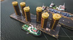
Examples of connectors.
Once the conceptual engineering design plans define how the equipment will be connected, 3D CAD tools are used to build the prototypes and check the interfaces among the components. It is important for offshore personnel or remotely operated vehicles to assemble and detach connectors quickly during installation. Therefore, special fittings or kits are sometimes specified.
Detailed design optimizes component sizing and allows weight savings to be achieved while maintaining the necessary safety factors. With this in mind, the recently introduced grade R5 chain, with a tensile stress over 1,000 MPa, has been applied successfully on numerous projects during the past two years.
The strength and fatigue of connectors for permanent systems need to be documented by testing and/or analysis.
FEA is carried out to verify the connectors’ structural integrity, often with an additional corrosion allowance. The fatigue life is then assessed using the corresponding S-N curves, load histograms, and the appropriate stress/load ratio obtained from the FEA.
Only after considerable testing and analysis are the designs approved and classified, after which, manufacturing drawings are generated, and then the connectors can be manufactured for use in the field.
