SWEDEN Alternative Energy: Wind-powered generator could ease carbon dioxide tax burden on installations
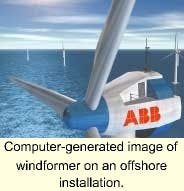
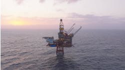
Computer-generated image of windformer on an offshore installation.
A new approach to the design of wind turbines has opened the possibility of their use offshore. ABB Corporate Research, based in Västerås, Sweden has investigated the alternatives to current wind turbine design and concluded that permanent magnets hold the key.
Following a major development program the company has created a wind-powered generator called the Windformer. The claimed performance level could make it ideal for use on offshore installations where conventional power generators can also generate high carbon dioxide taxes for their operators. The Windformer system could also bring benefits if used to support other types of offshore installation that do not have convenient access to hydrocarbon-generated electricity.
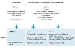
Windformer was created specifically for use in wind farms situated offshore and in coastal areas. Wind turbine benerators (WTGs) with Windformer have a high output of typically 3-5 MW. Key to the design is the Windformer's variable-speed rotor, with permanent magnets, that is connected directly to the turbine. The voltage produced by the generator is converted to DC by means of diodes. When used to support a utility grid on shore, the WTGs are connected in groups with the power being transmitted by cable to a network station with inverter that is linked directly to the grid.
Windformer was conceived as a "simple" technology incorporating stable systems that supply energy with high reliability and low losses. A cluster of WTGs would typically be connected to a high voltage utility grid through an inverter located in a network station where it could be accessed easily for maintenance and service work. The network station controls the real and reactive output individually making it possible to connect the wind farms to even a weak network. With Windformer technology, variations in wind speed or tower shadow due to other WTGs will not cause fluctuations in grid voltage.
By using an inverter to control the DC voltage, the generator speed is indirectly regulated, optimizing energy production in the process. The turbine blades are pitch-regulated although the main use of regulation is to adjust the input power to prevent turbine overspeed. A permanent magnet rotor converts the kinetic energy to electrical power. The generator is connected directly to the turbine and operates at a frequency in the range of 5-10 Hz. The choice of voltage, which is at least 20 kV, depends on the optimization of the Windformer system. A diode rectifier converts the low frequency AC voltage to DC.
A typical Windformer wind configuration would comprise several clusters, which in the original layout would have a rating up to 40 MW. As an example, a conventional utility scale wind farm in use today on land would typically consist of 10-100 WTGs, delivering 500 kW to 2 MW each with asynchronous generators rated at 0.7 kV. The generators are connected in series with a step-up transformer. In a large wind farm a substation transformer steps the voltage level up to 130-230 kV.
By comparison, the ABB Windformer power system has several distinct advantages:
- It exhibits low losses
- The power electronics in each WTG are reduced to a minimum, thereby increasing availability
- AC flicker in the network is reduced and the real and reactive powers are controlled separately. In short, the land-based regulating system optimizes the energy output for an entire wind farm whereas the systems controlling the Windformer regulate the power output of each individual WTG.
Pilot installation
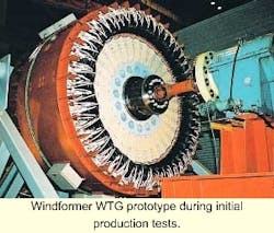
Windformer WTG prototype during initial production tests.
A pilot Windformer installation is to be installed soon at Näsudden, Sweden in a project supported by ABB, Scanwind, Vattenfall and the Swedish National Energy Administration. This will be an offshore version of the design but built entirely on land to facilitate the comprehensive evaluation and testing programs that are needed. Each turbine will have three 90-meter blades made of glass fiber epoxy with a hub height of 70 meters.
The WTGs will have a rated output of 3.0 MW which will be increased for offshore applications. They will be capable of functioning within a wind speed range of 5-28 m/s at variable speed - the rated output is reached at a wind velocity of 13 m/s. Below the rated turbine speed, the blade angle is kept in the most efficient position whereas at rated speed the blade is turned towards the "feathered" pitch position to limit the power output.
The output power is gradually reduced from 3 MW to 500 kW for wind speeds between 18 and 27 m/s. This has only a marginal effect on the annual energy production but helps significantly to optimize the life of the WTG. Annual energy production with such a WTG located offshore is calculated to be around 11 GWh based on an annual mean wind speed of 8.0 m/s.
One of the factors restricting the use of large wind turbines on land is the difficulty that is often associated with manufacturing and transporting the various components. In addition to the environmental benefits and the more consistent availability of an adequate wind speed, an important advantage of offshore power generation is that there is no logistical restriction to the size of the turbine blades. The problem of identifying a route needed for transporting rigid turbine blades 90-meters long to a site on land can often be formidable.
No-gear generator
Another important component of the Wind-former is a cable-wound generator connected directly to the turbine - this is an adaptation of an ABB generator design known as Powerformer. In this design, the variable speed of around 18 rpm reduces stresses as well as noise emissions at low wind speeds. Windformer does not have a gearbox, thereby reducing both losses and maintenance. By comparison, a conventional gearbox-driven 1500 rpm fixed speed generator rotates the same number of times in one month as the direct driven Windformer WTG does in ten years.
Windformer's smaller number of vulnerable components contributes to its extremely high reliability and availability. These characteristics and the reduced maintenance are vital for offshore applications where access to the WTG might be limited. Special measures have also been taken to ensure that the generator withstands severe climatic conditions such as constant dampness and salt air.
The stator employs round cables instead of square insulated copper conductors as in a conventional generator. The entire Windformer generator is constructed without cable joints and since the electrical field is totally confined within the cable there are none of the usual problems with discharges at the end windings and connections experienced with conventional generators.
Lower losses
Losses in the windings are lower due to the higher voltage level. Use of cables also reduces the risk of phase-to-phase faults. The concept in itself reduces short circuit currents and there are fewer safety issues involving the generator because of the small number of electrical components.
The ABB Powerformer technology upon which the Windformer design has been based induced the magnetic flux in the rotor by coils on the pole cores. The magnetizing current and the slip rings that are required were identified as a direct cause of electrical losses.
In Windformer, the stator's magnetic field is produced by permanent magnets and auxiliary equipment for inducing the magnetic flux in the rotor circuit is unnecessary. A rotor with permanent magnets does not need to be cooled since the losses are low. In addition to improved efficiency, the permanent magnet rotor offers other advantages such as better availability, high reliability and reduced maintenance.
During development of the Windformer generator special attention was given to optimization of the magnetic circuit. This included sizing the circuit to avoid de-magnetization of the permanent magnets. The rotor is multi-polar with a large air-gap diameter of over 6 meters making it what is probably the largest permanently magnetized rotor ever manufactured.
Numerous variations have been introduced to adapt Windformer for offshore operation. These include the use of a corrosion resistant material for the permanent magnets that will withstand the harsh environment and minimize maintenance. The Powerformer stator cable windings are also designed to resist the harsh marine climate so that there is no risk of electrical flashover.
For more information, contact Mikael Dahlgren, tel +46 21 323 276, fax +46 21 137 665, E-mail mikael.dahlgren@ secrc.abb.com

