Project offshore Qatar extends horizontal drilling limits
David Brink, Barry Gabourie, Morten Hesselager Pedersen - Maersk Oil Qatar AS
M. Rushdan Jaafar - Qatar Petroleum
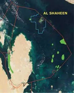
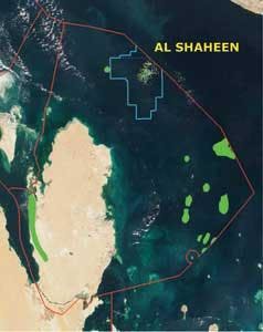
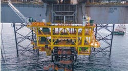
Maersk Oil Qatar is operator of Al Shaheen field on the central axis of the Qatar Arch some 70 km (43.5 mi) northeast of the Qatar peninsula. The main production targets are the Lower Cretaceous Kharaib B and Shuaiba carbonate formations and the Nahr Umr sandstone. The field is being developed with long horizontal wells because of the following:
- The large areal extent of the accumulation
- Poor vertical well productivity
- Number of platform locations required for a conventional approach.
The Al Shaheen development is ongoing from nine platforms, which was made possible only by drilling extended reach wells. The length of these horizontal wells has been extended during development, and some of these wells push the limit of what can be achieved with today’s technology. Implementation of multi-lateral wells has the potential to further optimize the development by reducing the number of required drilling slots, saving on top-hole costs, and reducing operational expenditure due to the decreased number of wells. All this can be achieved while maintaining the very long horizontal sections already employed in the single lateral wells.
Multi-lateral well philosophy
The initial motivations to drill multi-lateral wells were twofold. First, there are a large number of wells being drilled as part of the current field development plan (FDP). As the development progresses, more opportunities are being identified to optimize recovery by drilling wells. It was foreseen that these additional wells and wells planned for future phases of the FDP could result in platform slot constraints at some locations. Second, drilling rig day rates have increased to unprecedented levels, which makes the cost of drilling tophole sections significant. This increases the potential cost savings from reducing time spent tophole drilling and also benefits by accelerating production. As planning progressed, it also became apparent that multi-lateral wells could optimize the development of some sections of the field due to benefits associated with well pattern positioning.
Junction selection
After reviewing various multi-lateral options, it was concluded that Technical Advancement of Multi-laterals (TAML) Level 2 junctions were optimum for this development. These junctions are simple and relatively risk-free compared to higher level multi-lateral junctions, provided the cement quality of the motherbore casing is good. There is no mechanical or hydraulic integrity at TAML Level 2 junctions. However, this is not required for these applications. Multi-lateral wells of this design have been used extensively in the Middle East with few failures. Furthermore, service providers in the region are geared for this type of installation.
Well construction
The two TAML Level 2 multi-lateral wells drilled to date in the Al Shaheen development have 20-in. (51-cm) conductor, 13-3/8 in. (34-cm) surface casing installed down to the Laffan formation, and 9 5/8-in. (24-cm) production casing with the shoe set in the reservoir section accessed by the well. A tangent section is planned at the sidetrack depth to provide an area optimal for setting and retrieving the whipstock. The tangent section is planned to be long enough for the primary exit point as well as a contingency exit in the joint above, should the primary exit fail. The reservoir section in the motherbore and the lateral are drilled with an 8 1/2-in. (22-cm) bit. Both the motherbore and lateral sections are stimulated with 15% hydrochloric acid using an acid jetting assembly on drill pipe. The motherbore section is stimulated prior to setting the lower isolation packer which also serves as the whipstock anchor. The whipstock is installed, the casing window milled, and the lateral is drilled. The lateral is stimulated prior to pulling the whipstock and completing the well.
Completion design
Reservoir control is important for both production and injection wells in the current development plan, so individual control of each lateral was a requirement from the outset of the multi-lateral well justification process. Due to the extreme trajectory of the wells, manipulation of interval control valves (ICVs) with conventional slick-line is not possible and is limited with coiled tubing. Throughout much of the development plan, jackup rigs are in place over many of the wellhead platforms, making access for coiled tubing intervention expensive. For these reasons, surface operated ICVs were selected for installation in multi-lateral wells and multi-zone single lateral wells. A hydraulic system was chosen with a common return line and simple on-off function, although variable choking valves now are available also for installation.
The lowermost ICV is a shrouded type which allows it to be positioned above the bottom isolation packer. This offers several advantages over a conventional ICV, including the following:
- Saves rig time by a) installing the ICV shallower, and b) avoiding control line feed through the lowermost packer
- Avoids the risk of running control lines past the milled casing exit where they could be damaged
- Allows installation of the lower-most packer prior to drilling the second lateral. This packer can act as a base for the whipstock and can isolate the first lateral while drilling the second lateral. Hydraulic wet connects could achieve the same result while using a conventional ICV, but with the risk of a bad hydraulic connection in the debris-prone environment of a milled casing exit.
To confirm position of the ICVs and to gain information on which lateral is contributing to flow, a permanent downhole pressure/temperature gauge is installed for each lateral as is one for commingled flow in the tubing string.
Implementation
The two multi-lateral wells drilled to date in Al Shaheen field are water injectors, but are back produced initially, as is standard practice for injection wells in the development.
Multi-lateral Well A was a medium-length extended reach trajectory, with both laterals drilled beyond 15,000 ft (4,572 m) MD in the Kharaib B carbonate reservoir. This reservoir is characterized by a fairly homogeneous permeability distribution with typical values ranging between 5 and 10 md. Despite variance in fluid properties, well liquid Productivity Indices (PIs) generally are evenly distributed around a mean value of 3-5 b/d/psi. The uniform inflow performance makes the Kharaib B reservoir technically suitable for multi-lateral wells.
The first well was a learning experience, and all operations were done with the idea of successfully completing the first multi-lateral well. The drilling team and multi-lateral service provider worked closely to prepare for the job. Operational procedures were scrutinized and “Drill the Well on Paper” meetings were held to ensure everyone in the project was aware of the procedures to be followed. All equipment was laid out in the workshop and inspected prior to sending it out to the rig. The implementation proceeded as planned with only minor operational issues.
Multi-lateral Well B was planned as a long extended reach well, with both laterals drilled beyond 25,800 ft (7,864 m) MD in the Shuaiba carbonate reservoir. This reservoir is characterized by large facies variations with permabilities from less than 5 md to several Darcy in the areas dominated by reefs. The location of the line drive pattern in which Multi-lateral Well B was drilled is, however, positioned in a basinal area dominated by a homogeneous permeability distribution with typical values ranging between 5 and 10 md. Fluid properties and therefore liquid PIs also are distributed evenly around a mean value of some 10-15 b/d/psi. The regional uniform inflow performance makes this Shuaiba reservoir location technically suitable for multi-lateral wells.
The lessons from the first well were implemented in planning for the second well. The procedures and equipment again were checked prior to the job. The same personnel were involved for the operator and the service provider to assure that all lessons learned from the first well were carried through to the second well.
The multi-lateral operations were identical to Multi-lateral Well A. The main difference from Multi-lateral Well A to Well B was the length of laterals. The mainbore was drilled to 26,700 ft (8,138 m) MD and the lateral was drilled to 25,880 ft (7,888 m) MD. Extended reach drilling added new questions to the durability of the equipment and to the ability to recover the whipstock after drilling across it for an extended period. However, implementation was without incident.
Case studies
Well A
Upon completion, Multi-lateral A was produced with both laterals flowing to allow efficient clean up and to enable benchmarking against existing wells. The performance of Multi-lateral A met expectations, with oil production approximately twice that of adjacent wells. Consequently, the well was initially kept on comingled production from both laterals to maximize production.
Subsequently, an adjacent well produced with an abnormally high water PI and it was decided immediately to test each lateral (ML1 and ML2) in Multi-lateral Well A selectively to further interpret production performance. Prior to testing, the laterals were shut-in intermittently to accurately determine localized reservoir pressures, thus allowing subsequent calculation of productivity indices.
The acquired test data, in terms of liquid, oil, and water PIs, demonstrated a significant performance difference between the two laterals, benchmarked against each other and against typical wells with similar reservoir exposure.
Based on typical reservoir homogeneity it was concluded that the PIs of both ML1 and ML2 were the result of a localized secondary permeability, and the difference between the laterals was a consequence of its areal distribution. It was further concluded, considering the repeatability of the observed behavior, that porosity associated with the secondary permeability system was most likely charged with water during shut-ins, then immediately drained when the respective lateral was re-opened for production. Thus, such a mechanism would explain the high and rapidly declining water PI profiles leading to the stabilized PIs representing the total dynamic performance under “equilibrium”, i.e. controlled by the matrix feed rate into the wellbore and into the high permeability system.
The identification of an unexpected localized high permeability system initiated a comprehensive review of static and dynamic data, which led to evidence of a similar system in nearby wells. Based on geological and petrophysical characterization, the permeability system was interpreted as being the result of a complex network of micro-fractures providing a substantial enhancement to the conductivity of the carbonate matrix itself.
The capability to test the two laterals individually without requiring well intervention or high-resolution pressure gauges enables high-level reservoir characterization in terms of lateral confinement of the distribution of a localized micro-fracture system.
The micro-fracture system significantly impacts local fluid dynamics and its identification and delineation carries high significance in planning the remaining well in the area under development.
Well B
Upon completion, Multi-lateral Well B was produced with both laterals flowing to allow efficient clean-up and to enable benchmarking against existing wells. Performance of Multi-lateral Well B was similar to adjacent producers, which was below expectations considering approximately twice the reservoir exposure.
As a consequence of the poorer-than-expected performance, it was decided to immediately test each lateral (ML1 and ML2) in Multi-lateral Well B selectively to further interpret production performance.
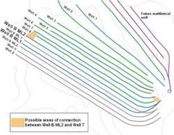
While testing ML1, two shut-downs were experienced, the first affected only Multi-lateral Well B while the second affected the entire field. While shutting in Multi-lateral Well B at surface did not induce any change to the ML2 bottomhole pressure build-up trend, a clear response was observed immediately upon field shut down. These observations provided evidence that ML2 was communicating directly to another well. A review of nearby well events was conducted. Based on a combination of pressure and production data, it was concluded that ML2 was linked to nearby Well 7, a planned water injection well which was on back production prior to conversion. Interestingly, this connection bypassed the producer Well 8 in between, indicating that the communication was either at the heel or toe of the well.
The instantaneous nature of the pressure response in Multi-lateral Well B ML2 following operation of Well 7 suggests that the communication path is very direct, e.g. through a fracture with practically infinite conductivity rather than through the matrix. The existence of a fracture was unaccounted for, as no drilling, geological, or petrophysical evaluations gave any such indications.
The ability to test the two laterals individually without well intervention and the presence of high-resolution pressure gauges has enabled state-of-the-art reservoir characterization in terms of accurately identifying direct communication between two existing wells.
The existence of interwell communication caused by extreme permeability variance implicates efficient implementation of secondary or tertiary recovery processes. Well interventions typically are required to resurrect adequate reserves recovery. Particularly in multi-lateral wells often with limited or no options for re-entry, such interventions are difficult or impossible, so have a low chance of success at best. The only option with the installed completion is to shut off an entire lateral. In the case of Multi-lateral Well B, the impact of the communication was minimal, as short circuiting of water between two injectors, at least theoretically, should not be critical when occurring without interference with the intermediate producer. These reduced implications in Multi-lateral Well B do not change the fact that the presence of unexpected reservoir geology imposes one of the biggest risks to successful implementation of multi-lateral wells, and reemphasises the need for a thorough candidate selection procedure.
Concluding remarks
The first two TAML Level 2 multi-lateral wells in Al Shaheen field were operational successes from the drilling perspective. All the equipment worked as planned, and there were no lost time or safety incidents.
Lessons learned and action items include:
- Extensive planning and operations preparation were essential to ensure successful multi-lateral well construction
- Lessons learned during the construction of Multi-lateral Well A were carried forward to Multi-lateral Well B to further enhance success of the operations
- Efforts are under way to replace the shrouded ICV with a ball-type ICV, which would remove the flow restriction inherent with shrouded ICVs
- The ability to test the two laterals individually without well intervention and the presence of high-resolution pressure gauges has enabled state-of-the-art reservoir characterization giving Multi-lateral Well A identification and lateral confinement of a localized micro fracture system and in Multi-lateral Well B, accurate identification of direct communication between two existing wells
- Unexpected reservoir geology imposes risk on the success of multi-lateral wells and re-emphasises the necessity to implement a thorough candidate selection procedure.
Acknowledgement
The authors thank the management of Qatar Petroleum and Maersk Oil Qatar AS for their encouragement and permission to publish this work.
Editor’s note: This article is a summary of the paper presented at PennWell’s Offshore Middle East Conference & Exhibition 2008 in Doha, Qatar. www.offshore-mag.com.
