M. Thompson, L. Amundsen • Statoil ASA
H. Nakstad, J. Langhammer, M. Eriksrud • Optoplan AS
A multi-component fiber-optic seismic acquisition system has been developed and qualified in a joint venture between Statoil ASA and Optoplan AS. The seismic sensors were based on fiber-optic sensor technology, i.e. each 4C ocean bottom seismic station consists of a 3C fiber-optic accelerometer and a fiber-optic hydrophone.
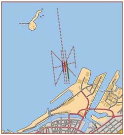
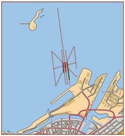
Two qualification experiments were carried out. The first was in 40 m (131 ft) of water off Trondheim, Norway. Two fiber-optic cable units were deployed and for comparison a system based on MEMS technology was deployed in parallel. All three cables were buried at a depth of about 1 m (3.3 ft) into the seafloor. Seismic data were generated using a selection of single airguns towed from the Norwegian geological survey vesselM/V Seisma.
The second experiment was in approximately 300 m (984 ft) water depth off mid-Norway. This fiber-optic OBS cable was buried to a depth of 1 m (3.3 ft) into the seafloor and the fiber-optic lead-in cable was brought ashore to the active top-side instrumentation. Seismic data was generated using a full size seismic source array commonly used in commercial seismic OBC acquisition settings.
Data analysis
The fiber-optic OBS system data was compared in quality with data from an electrical system, which was deployed in conjunction with the first experiment. Key issues in the data analysis were vector fidelity, system frequency response, intrinsic system generated noise, signal-to-noise ratio, and ground-station coupling.
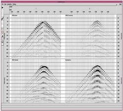
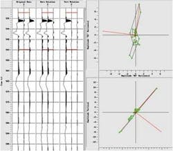
Analysis showed clean, high-quality raw data, where both the frequency content and the quality of the data from all stations appear to be uniform. This indicates very good coupling of the buried stations to the seafloor and high signal-to-noise ratio. Hodogram analysis was carried out on the data with excellent results, and the data were rotated successfully using vector rotation based principles. Both the hodogram analysis and vector rotation indicate that the fiber-optic OBS system had good coupling to the sea floor and excellent vector fidelity.
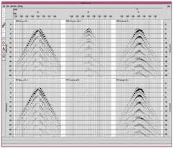
Common receiver gathers from a representative fiber-optic station. Components are: Inline (top left), Crossline (top right), Vertical (bottom left), and Hydrophone (bottom right). Source used was the BOLT 40-cu in (66-cu m) air gun and the shot line is parallel and straight over the receiver cable. Filter: 3 Hz (12dB/oct) – 160 Hz (72dB/oct).
The results are promising and represent a great step towards using fiber-optic sensor technology in ocean bottom seismic for reservoir time lapse studies. The analysis demonstrated that fiber-optic sensor technology can be used in ocean bottom seismic applications. The technology has been tested in two different settings and exhibits excellent vector fidelity, very good ground-station coupling and flat broad-banded frequency response. The data from this system show low noise and exhibit similar degree of vector fidelity to the reference system deployed in the first experiment.
These tests confirm that fiber-optic sensor technology is viable for applications within permanently buried seismic acquisition systems and can be introduced to the industry in connection with life of field seismic projects.
Prior tests
Multi-component fiber-optic sensors previously were demonstrated in connection with permanent in-well applications. One major advantage of fiber-optic technology over electrical technology is that the fiber-optic sensors are passive and do not contain electrical, or moving components, which may degrade and fail over time. This result in a significant reliability improvement compared to electronic systems. Instead, all of the sophisticated instrumentation is located at the surface, which makes it easy to maintain, and upgrades to the system will not require expensive and risky field operations.
The common receiver gathers for a fiber-optic station. At the top are inline, crossline, and vertical accelerometer data, and bottom are notated inline, crossline, and vertical accelerometers.
A permanent, buried ocean-bottom system using electrical sensors was tested at the Valhall field in the North Sea. The introduction of fiber-optic sensors to this acquisition concept may contribute to lower cost in-sea equipment as well as more reliable sensors and better data quality over time.
Acknowledgments
This is based on a paper presented at the 2007 EAGE annual meeting in London. The authors thank Statoil ASA and Optoplan/Weatherford for permission to publish this paper. We also thank our colleagues at Statoil ASA and Optoplan AS for their hard work throughout the project, as well as NGI, NGU, and BOLT Technologies for support. The Trondheim Harbour Authorities are acknowledged for their permission to conduct the test in the harbor area.
