Overcoming float-over challenges
Topsides installation method offers alternative
Alp Kocaman, J. Ray McDermott Inc.
Float-over topsides installation has become a cost-effective alternative for offshore construction over the past 25-30 years, as ever-increasing topsides weight constantly exceeds the lifting capacity of floating cranes.
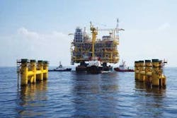
The basic concept in the float over is to transport the topsides on a vessel in one piece, position the vessel over the substructure, and lower the topsides onto the substructure while maintaining the position of the vessel.
While this basic principle of load-out and transportation remains the same, methods and systems used to execute the concept vary significantly, and pose numerous technical and operational challenges.
Float-over phases
From an operational point of view, there are several distinct phases:
- Standby - The vessel is a safe distance from the substructure but connected to the mooring system, and last minute preparations such as preparing the vessel’s rapid ballast system or the hydraulic jacks are under way
- Docking - The vessel enters the substructure
- Pre-Mating - When ballasting the vessel to match the leg mating units (LMU) with receptors on top of the substructure legs and removing the remaining tie downs, it is critical that the vessel motions be limited to suit the chosen LMU geometry. No weight transfer yet occurs
- Mating - The topsides is lowered onto the substructure by either rapid ballasting of the vessel or by contracting the hydraulic jacks. The topsides weight is transferred to the jacket completely
- Post-mating - A gap is created between the deck support units (DSU) and the vessel to ensure vessel motions will not cause contact between the two
- Exit - The vessel is removed from the jacket slot.
Float-over vessel
The vessel is critical for a successful float-over operation. This vessel will be used to load out the topsides, transport it to site safely, perform the float over, and return. Although there are a number of self-propelled vessels used in float-over operations, the majority are accomplished using typical cargo barges. In some cases, multiple vessels in catamaran or trimaran configuration have been used.
The float-over vessel must be narrow enough to fit inside the jacket legs, but have enough strength and stability to load out and transport heavy topsides. The recent large-sized topsides (15,000 tons [13,608 metric tons] and heavier) usually have jacket leg clear spacing of around 151 ft (46 m). Assuming nominal clearances, the vessel width is limited to no more than 138 ft (42 m). The vessel also needs enough strength and stability to load out and transport such heavy topsides, which usually require a wider vessel.
The use of hydraulic jacks allow the topsides to be towed to site on the transportation vessel low and raised to float-over elevation just prior to the float-over operations. This can be critical for topsides with a high vertical center of gravity, where stability during the tow is marginal or unacceptable. The hydraulic jack system also provides speedy lowering of the topsides. However, being an active mechanical system, the jacks have to be built, maintained, and controlled at a high precision.
Sand jacks are another method to rapidly separate the transport vessel from the underside of the topsides. Sand jacks are large diameter pistons that rest on a sand column to support the entire weight of the topsides. When sufficient weight has been transferred to the substructure, trap doors are opened to dump the sand and lower the piston rapidly to complete the weight transfer. Sand jacks are more cost efficient than hydraulic jacks.
Unless a hydraulic or a sand jack system is used to lower the topsides, the weight transfer usually is accomplished by ballast transfer. A rapid ballast system (RBS) that has been used recently reduces the duration of weight transfer for 20,000-ton (18,144-metric ton) topsides to about 20 minutes. An added advantage is that it is a failsafe system; once the valves are opened there is no need to control or close them until the barge separates from the topsides.
Float-over hardware
A number of components are needed for successful mating of the topsides with the substructure.
Deck support frame (DSF) is used to distribute highly concentrated topsides leg loads into the vessel frames. A plate girder type distributes load along four longitudinal bulkheads of the float-over vessel and can handle high topsides leg reactions. In other projects, tubular space frames have been used with success.
The topsides are supported on the DSF using deck support units (DSU). The DSUs also can be configured with or without shock absorbers, depending on the separation mechanism. Compliant DSUs rest on a low friction surface, allowing the vessel to move freely during separation. This decouples the mass of the vessel from the topsides so the vessel’s inertia does not add lateral loadings to the top of the jacket via the leg stabbing points.
Leg mating units (LMU) are the shock-absorbing devices placed inside the topsides leg tips and make contact with the receptors at the top of jacket legs. Shock absorbing LMUs are specially designed rubber elements that prevent shock loads from overstressing the topsides structure. In other cases, depending on the geometry limitations, the LMUs may be placed inside the jacket legs.
Mooring system
A mooring system needed for most float-over operations should be sized to comply with the expected vessel motions, site environmental conditions, and the geometry dictated at the site. Mooring lines are made up of either steel or polypropylene lines terminating at steel ropes.
The lines and their pretensions are calculated and adjusted to provide precise positioning of the vessel and to minimize the motion effects of the environment. The natural period of the vessel needs to be checked to make sure there are no resonance issues.
The mooring system must be small enough to be deployed and disconnected easily on location, while strong enough to maintain vessel control. Typically, mooring winches of 120-ton (109-metric ton) pulling capacity and wire size less than 2-2.5 in. (5-6 cm) in diameter are selected. Anything larger will be difficult to handle offshore or will require special winches. For smaller mating lines that terminate at the jacket legs, 50-ton (45-metric ton) capacity winches work well.
There are two methods to control vessel motions. The loose slot method uses vessel mooring lines and mating lines to control vessel lateral motions, therefore, no special fender system is required. The clearance is sufficient to ensure the vessel will not contact the jacket legs during maximum vessel motions. In this case, a proper mooring arrangement is required to make sure the vessel does not contact the jacket. Computer simulations and model tests normally are required to make sure the vessel does not contact the substructure or if the contact occurs under a contingency scenario, the vessel and the substructure will not sustain detrimental damage.
The second method, tight slot, puts a small clearance between the vessel and the jacket by installing several fenders in lateral direction to restrict vessel movement in both surge and sway directions. The fenders prevent vessel movement and absorb the energy created by the vessel motion. In this case, the elastic property of the system will include the fenders and the stiffness of the jacket legs. Longitudinal stops also are placed to arrest the surge motion of the vessel. One disadvantage of the tight slot method is the possibility of the vessel getting stuck in entry or exit phases of the operation.
Analysis methodology
In the analysis of the float-over operation, the vessel motions and the resulting loads in the LMU, DSU, and mooring lines need to be estimated. For most motion analysis software the vessel hull needs to be defined as a collection of panel plates. The topsides can be modeled as a rigid body. The program needs to have means to connect the topsides and the vessel using rigid and flexible connector members, as well as the mooring lines.
The analysis program then has to put all the components together:
- The barge will be connected to the seafloor by mooring wires
- The barge will be connected to the jacket using mating lines, or fenders if a tight slot method is being considered
- The topsides will be connected to the barge using rigid connecter simulation
- DSU will contain vertical gap spring and lateral spring element to simulate a frictional surface between the topsides and the barge
- The topsides will be connected to the jacket using LMUs
- LMUs will have a nonlinear gap spring element considering mating cone and receptor geometry and ability to generate side loads.
To predict the motions and related connector loads, 3D time domain analysis can be used, modeling the float-over system as three independent rigid bodies with different types of connectors. For the hydrodynamic calculation, 3D diffraction method is applicable.
By applying wave, wind, and current environment, the motions of the bodies under study (in this case, the float-over vessel and the topsides) and the forces in the connectors can be predicted. Statistical analysis of the results provide the upper, lower, and nominal values and, thereby, the design basis.
Model testing
In most instances, computer simulations will not sufficiently assess the feasibility of the float over nor establish the design criteria for the individual components. Model testing is a good way to verify that the computer simulations are realistic and no surprises are incurred.
The model scale must be selected carefully. The wave heights and the swell heights to be used in prototype scale are small, less than 7 ft (2 m). Scaling the waves to model scale will produce very small waves at low periods, which will be test-facility limited to add further complications. Recommended maximum scale is 1:50. Even at that scale, the model scale waves will be 1.2-1.6 in. (3-4 cm) in height and 1 second in period. Creating such a small wave is difficult.
Modern instrumentation techniques and digitized data collection offer great advantages. Significant amounts of operational data can be collected and processed easily. As a minimum, the motions of the topsides and the barge will be measured. The optical tracking systems widely available today also allow for determination of the velocities and accelerations.
The forces between LMUs and DSUs can be measured with relative ease. Loads on the mooring lines and the mating lines can be recorded as well.
One of the technical challenges of the model testing is interpretation of the results and correlation to the computer simulations.
Limitations
Each component of a float-over system will have physical limitations in terms of maximum motions or loads. When these limits are exceeded, safety will be compromised. An iterative process can establish these limitations.
LMU and DSU component geometry determine the motion limits. Maximum LMU excursion radius is restricted mainly by the substructure leg diameter. The maximum excursion radius rarely exceeds 3.3 ft (1 m).
Vertical and lateral load limits on the LMU and DSU components are determined by the substructure and the topsides structural strength. Usually, the float-over vessel and the specific analyses are not available at the time of the topsides and substructure structural design, so the limits may be set based on past experience.
The mooring and mating lines (and fenders, if used) will have limits. Barge motion limitations need to be verified so that the vessel does not contact the substructure.
In the final analysis, the wave limits are established as a function of approach direction that will allow safe operations.
Determining the limiting weather conditions, especially the vessel motion limits, is important and needs to be established up front.
Mono-hull vessels are more sensitive to long period swells than to short period seas. Different regions of the world may have different weather data; using a spectrum peak period of around seven seconds gives a good split point between the two. Weather data needs to be analyzed; history for 100 years or more is obtained with a clear distinction to separate out the swell component, wind, and current speed distribution.
Based on the weather limitations for different directions of weather approach, for different times of the year, and for historical installation site weather data, the next step is to look at the potential workability for the float over. Although the workability thus obtained will not be strictly deterministic, the resulting number will be guidance for the potential weather downtime for a given installation period.
Offshore operations are a critical phase of the total project. A set of procedures are needed to aid in the decision-making process offshore. In addition to regular site-specific weather updates, a wave rider buoy can be deployed to provide real-time data on the wave conditions and trends. This real-time data can be compared to historical data to see if the prevailing weather is better or worse, and contrasted to the initial workability percentages.
Another decision-making tool that can be installed is the vessel motion monitoring system. In this system, the real-time vessel motion in 3D can be viewed along with the trend. When the vessel motions are within the limit and the trend is favorable, the next step in the operations can be completed.
Real-life example
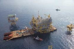
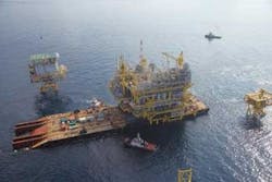
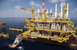
J. Ray McDermott recently completed the float-over installation of the largest integrated deck in Southeast Asia. The 18,739-short ton (17,000-metric ton) Arthit Process Platform (APP) was built for PTT Exploration and Production Public Co. Ltd. (PTTEP) at the J. Ray fabrication facility at Batam Island, Indonesia. Float-over was in the Arthit field in 262 ft (80 m) of water in the Gulf of Thailand, approximately 398 mi (641 km) south of Bangkok. The substructure (jacket) was fabricated by J. Ray’s Batam facility, transported and installed at Arthit.
With no barge readily available with capacity to load out, transport, and float over the Arthit deck, J. Ray McDermott used a system built specially for the project on theIntermac 650 (I-650) barge. Modifications included narrowing the I-650’s bow section from 170 ft (51.8 m) to 138 ft (42 m), allowing it to enter the jacket slot, while keeping the stern section intact to help maintain stability, load out capacity, and barge strength.
The deck was built low on the fabrication yard skidways to improve clearance for the cranes. For load out, the first step was to raise the deck and slide the DSF underneath it. The newly built DSF also served as load spreading grillage, properly distributing the deck weight into theI-650 frames.
The deck then was lowered onto the DSF and tie downs between the two were installed. Four sets of strand jacks were placed on one side at the end of the DSF and at the opposite end at the deadman structure at the barge bow. Each jack had a capacity to generate 900 tons (816 metric tons) of pull, enough to overcome friction.
After load out, the deck was secured by tie downs designed for 10-year return period extreme weather and installed at the longitudinal girders of the DSF. Tow distance was 551 mi (887 km) and tow duration was approximately five days. A 12,000 hp main tug and 7,000 hp secondary tug were used to tow theI-650.
The mooring system consisted of eight mooring lines terminating at seabed anchors, and eight mating lines terminating at jacket legs. A loose slot method was employed, using shock cells at the jacket legs, LMUs, and sliding surface DSUs.
A loose slot mooring system was used, allowing the vessel to enter and exit with only incidental contact. The weather was limited to 4.1 ft (1.2 m) significant wave height.
With proper weather window in the forecast,I-650 was moved from the standby position over to the substructure. A rapid ballast system, consisting of a series of 24-in. (61-cm) diameter butterfly valves in eight different tanks, lowered the barge at a high rate during weight transfer. The total float-over duration was less than 12 hours. Most of this time was spent preparing the barge systems for float over. Actual weight transfer took less than 15 minutes.
The vessel entered and exited with minimal incidental contact. Weather limits were established to keep the barge from contacting the substructure during float-over. Computer simulations and model tests ensured there would be no contact.
With all the innovation and challenges involved, successful completion of this floatover demonstrated that the modifiedI-650 and loose slot method are viable ways to install very large topsides safely, efficiently, and economically.


