Subsea stations could reduce cost, loads of long-distance umbilicals
Gabriel Beaudonnet
David Chilloux
Doris Engineering
Luc Rivière
Guillaume Delaëter
Total Exploration & Production
Subsea production requires injection of various chemicals and hydrate inhibitors conveyed from the topside production facilities to the subsea equipment via umbilicals. Chemical/methanol injection tubes enclosed within the umbilicals are designed to carry their products at a pre-determined flow rate and injection pressure.
Main parameters governing the composition of the umbilical (the size and number of hydraulic tubes) are tieback length (managing the pressure drop caused by frictional losses in the tubes); flow rate, especially for methanol or low dosage hydrate inhibitor (LDHI); and the pump discharge availability at the topsides, typically 345 bar (5,000 psi).
However, to accommodate the longer-distance tiebacks now in the planning stage - over 30 km (18.6 mi) for oil fields and 300 km (186 mi) for gas fields in remote regions - the umbilical will have a considerably larger and more complex cross-section. But, this raises issues:
Manufacturability. Umbilical assembly machines' handling capabilities for stainless steel tubes and other umbilical components are limited by diameter and number of bobbins. Multiple tubes can also lead to large and complex terminations for the tie-in to subsea facilities. A wider umbilical outside diameter, with its associated weight and stiffness, will make it harder, and possibly unfeasible, to manage the umbilical fabrication process.
High procurement cost. This is due to the number of stainless steel tubes required and the testing needed to qualify the umbilical section.
Installation. This may prove difficult due to the increased outside diameter and stiffness and size of the terminations, and the number of reels or carousels needed to install the umbilical sections may prove impossible to accommodate on a standard pipelay vessel reel or carousel. The weather window is another factor. All these issues may cast a doubt over the project's technical and economic feasibility.
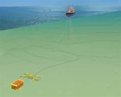
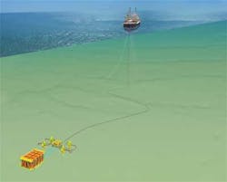
To reduce the umbilical cross-section and mitigate these various issues, Total and Doris propose a subsea station at various points along the route of the tieback for chemical storage and injection. The main goal is to locate these functions close to the subsea processing equipment in which the chemicals are to be injected. This would dispense with the need for chemical lines in the umbilical altogether, reducing its diameter and size and therefore lowering its weight, leading to lower procurement and installation costs. The concept also eliminates the need for a chemicals skid onboard the topsides facility, and allows improved local control over chemical injection.
Equipment and systems
The subsea station comprises subsea storage tanks; chemical injection pumps with flow control devices; piping for distribution of chemicals from the chemical storage tanks; a subsea control module for valve actuation, data transmission, and pump control; an electrical distribution module to supply the high flowrate chemical pumps with high voltage electric power; structure and foundation. Chemical refill operations would be performed periodically.
For oil field tieback developments, two types of chemicals are typically injected. Corrosion inhibitor, scale inhibitor, biocide and demulsifier are injected continuously into production lines, normally at rates of 6-20 l/hr. The exception is biocide, injected in batch mode and normally for 5 hr/week at 180 l/hr. Hydrate inhibitors, i.e. methanol and LDHI, are injected into wellheads, flowlines and jumpers, but only during well shutdown and/or start-up operations in order to avoid hydrate formation. They are typically injected at a much higher flow rate of 5-25 cu m/hr (1,321-6,604 gal/hr).
To accommodate these two injection modes and the varying amount of chemicals to be stored, two separate subsea stations would be optimum. One is a chemical injection station for storing chemicals applied continuously; the other is a shutdown/re-start station for storing hydrate inhibitors.
For gas field tieback developments, corrosion inhibitor, scale inhibitor, biocide, and monoethylene glycol (MEG) are all injected continuously. MEG, however, which must be injected into the gas stream at rates of up to several cu m/hr to prevent hydrate formation, the quantities involved render subsea MEG storage unfeasible.
Total and Doris applied the following philosophy for all aspects of the subsea station design:
- The subsea system must be modularized so that components requiring maintenance and replacement such as injection pumps, storage tanks, and electrical distribution modules can be retrieved to surface, replaced and tested, either as part of a module or as individual components. All modules must be independently retrievable and their weight must be limited to the capacity of a typical multi-purpose service vessel (MPSV).
- All interventions, including refills, to be performed with at least two pressure-containing barriers between the hydrocarbon source and the surrounding environment
- Equipment designed for access by work-class and inspection ROVs, with standardization (where possible) of equipment and interfaces
- Station to be protected against the impact of dropped objects, with protective covers and roof hatches supplied
- No interruptions permitted to chemical injection, particularly during refill operations. Two storage tanks and two injection pumps per chemical are to be provided to ensure continuous injection from one tank while the other is refilling.
The design team opted for a pressure-balanced design for the subsea storage tank, similar to a bladder or diaphragm tank, and made from a waterproof membrane or bladder. With seawater outside the tank acting directly on the fluid inside, the internal pressure is equal to the external seawater pressure. This allows the system to be much lighter than the alternative, a pressure-resistant tank which would have been too heavy for deepwater applications to 3,000 m (9,842 ft).
Another advantage of the pressure-balanced design is that the pressure at the seafloor acts as part of the injection pressure, allowing deployment of subsea injection pumps that provide for a lower differential pressure. However, the material used for the bladder would have to suit long-term chemicals storage and be compatible with the chemicals. There is no previous history of long-term storage subsea of large volumes of chemicals, but some existing systems might be adapted for the subsea station. For instance, pillow tanks used by the water, waste, and chemical storage industries are made from a high-tensile polyester fabric with elastomer coating - these tanks have a design life of up to 10 years. There are instances of small-volume chemical storage tanks used temporarily subsea for maintenance or pre-commissioning tasks.
One possibility for the subsea tanks is a design based on a rolling diaphragm bladder that minimizes the tank's external dimensions while providing sufficient volume capacity. When the tank is filled, the membrane inflates with the volume of chemicals pumped in, and an equivalent volume of water is expelled via a vent line on the outside of the tank structure. During injection operations, as the chemical is pumped out of the tank, the membrane deflates and seawater re-enters the tank structure through a dedicated line. The protective casing provides a barrier that isolates the bladder from the surrounding seawater, preventing contamination should bladder leakage occur. To facilitate pressure equalization, seawater circulates through dedicated lines, which can also be isolated if a leak is detected.
Injection pumps
The injection pumps, located on the subsea station, convey chemicals stored at seabed pressure from the station to injection points on subsea manifolds or christmas trees. Each chemical network has two pumps, one serving as a back-up for reliability purposes.
Volumetric positive displacement pumps are best suited to intermittent high pumping rates of up to 25 cu m/hr for methanol and LDHI, and continuous low pumping rates of up to 180 l/hr for chemicals. For the shutdown/re-start station (methanol and LDHI), the likely maximum power needed is 250 kW. As for the (continuous) chemical injection station, the maximum power range is 3 kW.
As no subsea chemical injection pumps have been designed for long-term use, the options are to marinize topside methanol injection pumps, qualified for long-term subsea application; or to adapt existing subsea pumps. Those employed on ROV-mounted chemical injection skids would be compliant with the flow rates and differential pressures required for the subsea station, but they are currently designed only for temporary deployment, and would have to be qualified for continuous injection.
To keep opex to a reasonable level, refill operations must be feasible from an MPSV that already performs inspection, maintenance, and repair tasks at the site. Equipment must not weigh more than 100 metric tons (110 tons) dry weight, within the typical MPSV crane capacity. Total/Doris considered three refill options. One involved use of a dedicated umbilical, which would allow relatively fast delivery of large volumes of chemicals to the empty subsea tanks. This option was discounted, however, because of the need for frequent reeling and associated flushing equipment onboard the vessel.
The most favored method involves retrieving depleted tanks and replacing them with new ones refilled ashore. This would allow the storage tank and bladder to be inspected and maintained during each refill operation. But volumes lowered would have to be less than 30 cu m (1,059 cu ft) to suit the crane. A third option is to undertake refilling using small transfer tanks, all suited to the crane capacity: these would be lowered close to the depleted storage tanks with chemicals transferred via an ROV-mounted pump.
One refill operation would likely be needed every six months at the start of field life, and every three months toward the end of field life, as the need for injection increases due to higher produced water volumes. Depending on the field's characteristics, operations could involve a mix of the tank change-out and transfer tank methods.
Although the overall dimensions and weight of the entire subsea stations are greater than standard subsea structures such as manifolds and christmas trees - the total weight ranges from 300-800 metric tons (330-882 tons), depending on the number and quantity of stored chemicals, foundation type, overtrawlable protection requirement - each individual module weighs less than 180 metric tons (198 tons), which allows installation by a standard subsea construction vessel. The planned subsea compression plants are substantially larger and heavier.
As for overall capex, studies suggest that for a long-distance tieback, the subsea station for chemical storage and injection could be up to 60% less costly than a conventional umbilical solution. With an all-electric configuration, the benefits increase further with only a power cable remaining in the umbilical.
In terms of opex, the subsea station is more expensive overall. However, field life evaluations suggest that the concept is commercially attractive for oil field developments involving subsea tiebacks longer than 30 km (186 mi), and gas field developments with tiebacks more than 100 km (62 mi).
Currently, Total and Doris are working on the design of the subsea station for two specific case studies:
- One 30-km oil field subsea tieback offshore West Africa
- One 300-km gas field subsea tieback offshore Norway.
Results are expected by the end of September.
Acknowledgment
Based on a paper presented at the Deep Offshore Technology Conference & Exhibition, held Nov. 27-29, 2012, in Perth, Australia.p

