3D modeling improves deepwater umbilical design dependability
A new approach to modeling umbilical behavior could help mitigate umbilical failure. This approach goes beyond the traditional cross-sectional analysis to encompass 3D lengths and to account for cross-sectional asymmetry. It improves confidence levels and helps avoid over engineering of dynamic umbilicals.
Umbilical failure can have far-reaching consequences because of the equipment and the range of functions that are controlled through umbilicals. Component failure can halt operations and can affect flow assurance. And failure in data transfer through an umbilical can interrupt communications and affect production control.
Preventing failure becomes even more important in deeper waters. As water depth increases, component replacement and repair is correspondingly more difficult and expensive. High levels of structural integrity need to be assured in the larger-diameter heavier umbilicals needed for these depths.
The need for design tools and processes to improve umbilical installation and operation success rates becomes more acute as water depth increases. Rigorous analysis and testing of umbilical designs are crucial to performance assurance and to failure prevention. And the analysis and testing should simulate as closely as possible the real-life conditions under which the umbilical will function.
Applying the new approach
The quest for greater accuracy has stimulated activity to develop 3D modeling and analysis capability on behalf of both individual companies and in a joint industry project with the Norwegian Marine Technology Research Institute, contractors, and oil companies.
A proprietary 3D analysis approach developed by DeepSea Engineering & Management has been shown to provide reliable confidence limits for dynamic umbilical design under tensioner crush loading during installation. The approach also simulates operational fatigue behavior.
Recently, DeepSea undertook to verify the F56 umbilical installed on BP’s Na Kika development in the Gulf of Mexico, currently the world’s deepest producing field. Given the umbilical’s size, there was a need for accurate assessment of both strength and fatigue criteria. The 3D model satisfied that requirement.
Conventional approaches to modeling umbilical behavior include assumptions about interactions among the internal components. Current design practices approach umbilicals as if they were single, homogeneous structures. This falls short of representing the actual behavior of the complex system of helically wound tubes and cables inside the umbilical.
Sophisticated numerical tools such as ABAQUS software can model the complicated geometry and interactions inside an umbilical. However, these types of software demand computing power that can make them impractical for modeling an entire length of dynamic umbilical.
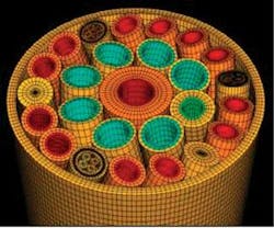
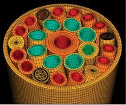
In DeepSea’s approach, the interactions between components are modeled along a 3D length of umbilical. Modeling includes the friction stresses because of their considerable impact on umbilical behavior and fatigue. This approach provides more accurate information about the interactions among components. Such interactions are especially important in large steel tube umbilicals with multiple counter-wound layers.
DeepSea’s 3D approach also assesses the installation conditions as the umbilical passes through the tensioner system because it captures the correct load transfer from the tensioner pads into all umbilical components.
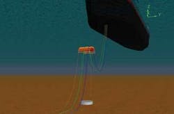
The approach combines proven industry tools with advanced finite element modeling. A global model of the umbilical system is constructed in an industry-recognized tool such as OrcaFlex software. Then, force and curvature time histories of the components are generated. The time histories are used as the input to local finite element models of the umbilical.
A 3D length of the umbilical under stress and tension then is modeled, with attention on how contact points, friction stress, and bending stress vary over time and position. Cross-section asymmetry - ignored in analytical assessments, but present in virtually every design - also is taken into account.
This approach delivers benefits at each stage of the process.
At the design stage, it allows operators to compare various umbilical designs. Until now, comparing different designs has been difficult because of the extent to which umbilicals can differ, e.g. unique features such as Aker Kvaerner’s plastic spacers to produce ‘no’ or low friction environments.
More accurate modeling also can result in targeted changes to technical specifications during design. This helps optimize performance and minimize manufacturing cost.
During installation, 3D modeling increases the confidence with which a project can proceed to umbilical laying. Modeling also can reduce installation costs and time because more precise assessments can be made of installation equipment and procedures. As a result, the pool of suitable installation vehicles could expand, which helps reduce downtime or delays.
Advantages of 3D modeling
Lessons learned throughout this project can be applied elsewhere.
For instance, the effect on the design from a fatigue perspective with regard to component placement of the following can be quantified and optimized within cable manufacturing constraints:
- Including a large diameter central tube (51 mm [2 in] and up)
- Configuring multiple large diameter tubes (greater than 25 mm [1 in] in cross-section).
Another example is the evaluation of the most appropriate (or proposed) tensioner arrangement, i.e. whether to use two, three, or four pads of what length, and the limiting load that can be applied through each pad. In particular, the asymmetric nature of an umbilical is most prevalent in a two-pad arrangement.
From design through operation, 3D modeling gives a deeper understanding of umbilical performance and technical risks. Modeling results in more informed design and installation decisions even in challenging environments such as deepwater, harsh environments, or when large steel tube umbilicals are required.
Because 3D modeling provides a more complete picture of the challenges and risks, it helps ensure that the engineering and testing undertaken confirms the reliability and integrity of the project without the costs and delays of over engineering.
This is particularly relevant in deepwater projects. Each system in a project (vessel, steel catenary riser, umbilical, etc.) has its “deepwater limit,” i.e. a water depth at which the assumptions and analytical tools that worked for shallow-water operational design and installation no longer hold. The ‘deepwater limit’ for each system is different. For DeepSea, the limit for umbilicals is around 1,272-1,524 m (4,500-5,000 ft), depending on project specifics, such as vessel type, umbilical size/weight, and harshness of the operating environment.
The DeepSea approach to 3D modeling of umbilical behavior in dynamic applications includes an analysis of where each system reaches its “deepwater limit.” Ascertaining these limits ensures that deepwater processes and techniques are included in the project design and installation only where they are needed.
Mark Dixon
Deepsea Engineering & Management Ltd.


