FRANCE: Steel hybrid riser extends flexibility in ultra-deepwater operations
Stephane Couprie
Francois Regis Pionetti
Xavier Rocher
Jerome Hugnot
Bouygues Offshore
As oil exploration and production moves into deeper waters, the main increase in terms of cost and technical risks will be associated with risers and flowlines. In particular, there will be:
- Increased installation difficulties
- Higher hydrostatic pressure (collapse pressure) during installation and production
- Higher payloads due to deeper and longer riser
- Soft soil creating difficulties at the riser/soil interface
- Flow assurance becoming increasingly a major concern.
One answer to these new challenges is a significant reduction in riser numbers, through connecting several wells to one single larger diameter riser to a floating production, storage, and offloading (FPSO) vessel. Steel catenary risers (SCRs) represent the simplest and most cost-effective riser system, but fatigue concentration at the touchdown point, as well as riser self-trenching on the seabed, jeopardize its reliability on most field developments.
The lazy wave SCR is an interesting alternative which promises to reduce riser movement on the seabed. However, this concept requires expensive buoyancy modules and the system then becomes very sensitive to transverse current. Flexible pipe has long been considered for deepwater, but its sophisticated structure makes it an expensive solution when water depth increases (due to collapse pressure and the need for sophisticated tensile armors). Also, feasibility has to be proven when high performance insulation, or corrosion resistance to hydrogen sulfide and carbon dioxide are required.
Girassol riser system
A major step forward has been the selection of risers for the Girassol project offshore Angola. In addition to the capability provided of gathering flowlines from several wells (with the possibility of creating production loops for circulation of oil or maintenance of lines), riser towers bring the following advantages:
- Elimination of the complex riser/soil interaction (main drawback of SCRs)
- Flexible jumpers can accommodate large dynamic relative motion between the FPSO and the tower.
Bouygues Offshore's "SHR'ewd" concept represents the next step forward for hybrid riser towers, which are emerging as the preferred solution for deepwater and ultra-deepwater developments, in terms of reliability, flexibility and cost-effectiveness. A key element of SHR'ewd is that it avoids use of complex flexible jumpers, which represent a significant cost constituent in hybrid towers.
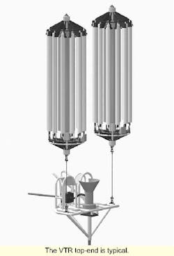
SHR'ewd is a hybrid riser consisting of a steel vertically tensioned riser (VTR) anchored to the seabed and a free-hanging SCR between the FPSO and top of the VTR. This combination has the benefit of a low stress level in the catenary riser (CR) sagbend, thus alleviating any potential stress or fatigue problems even for lifetime requirements in excess of 25 years. Stresses at the terminations and junctions of CR and VTR are drastically reduced through the use of flexjoints, which are now commonly used in deepwater risers. Two flexjoints are installed on the CR, one at each extremity, while a third provides a hinge at the seabed end of the VTR. The mid-depth CR flexjoint is integral with a gooseneck spool piece equipped with a male stab for automatic self-locking subsea connections to the VTR top.
Variety of pipe sections
Pipelines for the VTR and CR are primarily and independently designed to meet client specifications (pressure, temperature and insulation needs), in accordance with usual riser and pipeline codes. This design permits the use of any types of pipe section, from basic conventional pipelines to sophisticated high performance pipe-in-pipe (PIP).
Bouygues Offshore believes that the J-lay method is the most suitable installation scheme for such deepwater developments (minimal pipe preparation, virtually no residual stresses in the pipelines). SHR'ewd elements are designed for easier installation, and operations are fully reversible for improved reliability. The VTR length is engineered to minimize the sagbend stresses in the CR - the optimal elevation of the top of the VTR being then around midwater depth. At this level, where current effects are small and waves negligible, the buoyancy elements, made of syntactic foam and nitrogen ballast vessels, are installed in an optimal configuration, as stresses due to environmental conditions are kept to a quite low level.
Buoyancy elements
For the mono-SHR'ewd (described here as base case), the authors recommend use of two buoyancy elements. Each is composed of permanent syntactic foam cylinder in conjunction with hollow cylinders filled with nitrogen, in equi-pressure with the corresponding water depth. Connection and pressurization are performed by a remotely operated vehicle (ROV).
Multiplying the number of independent nitrogen floaters reduces the consequences of a failure. As a result, the VTR remains in an acceptable configuration even with one or two flooded cylinders.
The two buoyancy can sets are connected to a steel tubular frame by means of swivel joints or chains. Therefore, no momentum is being transmitted from the buoys to the frame. As an alternative to the base case, the buoyancy can be designed with a single tank surrounding the VTR top end. Buoyancy up-thrust is transmitted from the frame to the VTR through an anchor flange and a guiding sleeve. Located at the VTR top is a female half of a subsea connector for the connection of the CR gooseneck spool piece. Under the frame anchor flange, the VTR is fitted with a small stress joint which is needed to withstand local stresses due to the CR dynamics.
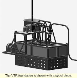
At seabed level, the bottom flexjoint of the VTR is locked in an angled receptacle on the foundation (which could be, for example, a suction-embedded pile or a gravity-based template). The link to the flowlines is provided by a spool piece fitted with a standard mechanical subsea connector, which allows thermal expansion. An alternative to the flexjoint is the use of a roto-latch system, instead of the flexjoint, at the VTR base.
A feasibility assessment and dynamic analysis performed by UK-based 2H Offshore Engin-eering demonstrated the following:
- The design riser is less sensitive to the environment than many existing riser systems.
- With the dynamic riser response reduced by the depth and the very low action of waves and current on the VTR buoyancy module, the design offers a high fatigue life with a considerable margin, even for 20-25 years' offshore service.
- Several risers can be installed side by side (20-30 meters), interaction between them not being an issue, as VTR depth and horizontal distance can be easily adjusted to avoid interference.
- In terms of riser dynamics and fatigue, the feasibility assessment demonstrates the design's suitability for use in water depths from 500 meters to 3,000 meters as prod-uction and/or injection risers.
Construction, installation
The SHR'ewd system has been designed to allow simple fabrication and to facilitate installation. It consists of three main items :
- Mid-water framing, including buoyancy cans
- Foundation, including deadweight and/or suction piles
- Two riser sections.
All elements related to the VTR and SCR are fabricated on site with a J-lay DP vessel or equivalent facility. The 50 meter quad-joints (conventional tubing or high performance PIP) can be easily manufactured close to the field, as local content, and then delivered directly on board the installation vessel.
The mid-water frame and foundation are conventional structure steel works. The buoyancy cans are made of syntactic foam blocks and standard pipe sections for the nitrogen ballastable units. All items, such as hydraulic components, mechanical connectors, and flexjoints are proven technologies, available off the shelf.
Installation of the system is preferably carried out with a construction and laying dynamically positioned vessel, but installation by any other DP vessel such as a drilling rig can be envisaged (although with reduced efficiency). The system has been designed for installation with optimal efficiency by Saibos' FDS, which is equipped with a J-lay tower for pipeline laying, and has lifting capacity up to 600 tons, additional equipment such as an ROV, and laying equipment for umbilical and electrical cables.
The system installation is an ROV-assisted operation, sequenced as follows. The foundation is lowered as a clump weight or a standard suction pile structure. The VTR is deployed from the J-lay ramp in a vertical position starting with a light clump weight (<10 tons) at its bottom end. The VTR is then transferred to the main ship's crane for installation of the frame and the buoyancy cans. At this stage, syntactic foam buoyancy is 100% efficient, ballastable cans are opened and filled with water.
Lowering is carried out with a main tension winch (capacity 400 tons). The VTR is then clamped and secured onto its foundation, using a light subsea winch operated by the ROV. Ballastable cans are then flushed with nitrogen at a pressure slightly in excess of local subsea pressure. They provide the necessary upthrust for the final configuration.
The catenary riser is assembled in one single vertical string from the J-lay ramp in a vertical position. The CR is designed so that its total length is smaller than the water depth (no interference with seabed nor abandonment on seabed that might create potential hazards). It is transferred vertically to the FPSO side or turret, and secured to its hang-off support. The CR's lower end connector is then pulled from the top of the VTR (return line to a winch on the construction DP vessel). It is subsequently connected to the mid-water subsea connector on to the VTR, and the automatic connector is then locked. Mobilizing a single construction DP vessel, complete installation of a 10 in. typical mono-SHR'ewd, can be handled by the FDS in 3-4 days
Cost comparison
To suppress costs, SHR'ewd's design is based on steel pipe, thus avoiding the use of expensive flexible pipes. Deepwater and ultra-deepwater present the following design issues:
- Higher diameters, as the natural trend is to minimize the number of risers
- Higher hydrostatic pressure
- Higher thermal insulation (flow assurance).
The complexity of the required flexible pipe leads to a drastic build-up of the riser. But increasing the nominal diameter of the system is not an issue and the concept is cost effective for small and large diameter risers in all deep water ranges, insulated or not. The system can be compared to hybrid risers employing flexible jumpers towards the FPSO. The cost of the flexible jumper has then to be balanced against the cost of the steel CTR, the two flexjoints (one at the FPSO, one at the top of the VTR), and the significant reduction of the VTR length.
The concept has been compared with conventional steel risers, such as SCRs, lazy wave, and compliant vertical access risers. These concepts can be envisaged for medium-to-deep water, but none of them is fully adapted to the strict requirements of deepwater and ultra-deepwater. Of course, SCRs are the cheapest, but they have limits in terms of thermal insulation possibilities, adaptation to soil conditions (interference at contact point), and they also exhibit a significant lateral excursion under the effect of current.
With regard to flow assurance, the most sophisticated Pipe-in-Pipe (PIP) can be used as basic components for both the SHR'ewd's VTR and CR. A different insulation technique can be also used for the VTR and CTR, and analyses have shown that the optimum cost is often obtained by using a highly sophisticated PIP for the VTR (no bending, virtually no movement) and a more conventional cheaper insulation media for the CR portion towards the surface.
Editor's Note: This is a summary version of a paper given at the 2000 Rio Oil & Gas Expo/Conference, held in Rio de Janeiro, Brazil.


