Drilling with casing offshore Congo
John Waggoner - Technology Editor, Drilling & Production
New bit technology has made it possible to drill with casing for the first time, representing a significant advance for reducing time and costs when new wells must be drilled and there are no more slots on the seafloor template.
A project off the coast of Congo in West Africa ran into this quandary when the operator wanted to drill another well to explore another structure of the reservoir to raise production but had no available slots.
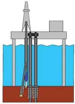
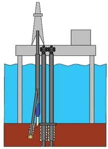
The project’s platform had a template with eight slots, all of which had directional wells drilled though a 30-in. conductor casing that was laid at the seafloor and connected to the platform’s drilling template. In order to secure an extra slot, the operator decided to set a 30-in. diverter with a 2° angle diverter on the seabed, so as to drill a new hole with a 26-in. roller cone bit. Then, 20-in. casing would be run and cemented through the diverter with free returns to the seafloor.
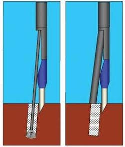
The problem was re-entering the 26-in. hole with the 20-in. casing due to the sag of the drilling assembly at the exit of the diverter, and the stiffness of the 20-in. casing.
The solution was an innovative technique: drilling with casing. This involved designing a special 24-in. casing drilling bit to be run through the diverter on a 20-in. casing string. With this approach, 66 m (217 ft) were drilled into the new formation at the 2º inclination with returns to the seafloor. The casing was cemented and the casing bit was then drilled out with a roller cone bit.
In this way it was possible to secure the extra slot and get out of the trajectory of the existing well, saving time and money.
Technique raises production
The new technology can help solve particular problems in vertical holes or tangent holes where deviation control is not needed, says Enis Aliko, area engineering manager for Baker Hughes, who participated in the project.
“These problems can include surface losses, difficulties in running casing to bottom in conventional drilling, depleted reservoirs, and in general situations where the window mud weight – fracture gradient is very narrow, platforms where there are no available slots on the template, etc.,” Aliko tellsOffshore magazine.
The technology has applications beyond West Africa and is being used very successfully in the Gulf of Mexico, North Sea, and Australia.
In the African project, the operator kept running into the dilemma of having to drill new wells with no more template slots.
The obvious answer was to drill new wells beside the existing wellbores and negate the use of a template, but since most of the field’s wells were deviated in different directions, there was the risk of collision with the template or existing wells, making it crucial to position the well precisely.
The operator decided to place a “deflector” conductor pipe on the seafloor and drill the surface section from a precut window. However, this solution meant passing 20-in. casing at this inclination through a 26-in. drilled hole and would almost certainly require days of remedial operations including trials, reaming, and even hole enlargement.
Underreaming the surface section from the beginning was possible, but this would create an uncommonly large hole for 20-in. casing, meaning large volumes of cement would be needed in the best case and possibly causing problems with centralizing the casing in the hole.
Faced with this situation, the operator decided to drill the surface section with casing instead of a conventional bottomhole assembly (BHA). The appeal of this approach was that the casing would guide the bit as it got further away from the window, reducing the amount of sag. Plus, the casing would already be in the hole. The drill size could then be reduced to allow drilling a 24-in. hole instead of 26-in., which was sufficient to house the 20-in. casing with and adequate thickness of cement behind it.
This solution meant that an entirely new casing drilling bit (CDB) had to be designed. One of the most critical factors was that it had to be tough enough to withstand drilling to the target depth. Were the bit to fail and the casing had to be pulled for repair, the economics of the operation would be shattered.
Custom PDC bit technology
The operator opted to go with a polycrystalline diamond compact (PDC) bit with premium PDC cutters. This was unusual for the region since the claystone and carbonates formations with occasional sandstone stringers are soft enough that a more economical steel-tooth roller would normally be adequate.
However, since the bit would drill with casing rotation and would have to be subsequently cemented in place and drilled out, a roller cone was not an option.
“Another option would be drilling with casing with a roller cone or PDC bit on a retrievable mud motor, and with an underreamer above the motor. There are also other ways of drilling with casing with a retrievable roller cone bit and without the motor, but they all require the use of the underreamer, and are more expensive, as well. The main advantages of the method we chose are its simplicity and its low cost,” Aliko says.
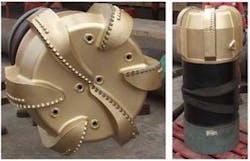
The CDB was designed with a special steel alloy body and a shank that incorporated a casing pup joint of the same size and properties as the main casing string. It had interchangeable tungsten carbide nozzles, an optimized hydraulic profile, custom gauge pads, and a safety nozzle with a rupture disc that could be hydraulically blown in case the face nozzles are plugged.
Other factors to consider were drilling hydraulics, torque, and drag, Aliko says. Since the annulus is smaller and equivalent circulating densities (ECD) can increase, there would be a higher risk of lost circulation. Torque and drag management was essential because standard casing connections lack the torque rating of BHA connections, making it imperative to keep any excess torque by the CDB in check.
“We used our analytical models to calculate the torque this bit could have developed in this formation and were confident that the 20-in. casing would handle that torque. In fact, there were no problems whatsoever,” Aliko says.
The chosen design was for a 24-in. CDB with a six-blade bit and 13-mm (1/2-in.) cutters, and as no such design existed it had to be specially produced. The PDC also had six interchangeable nozzles and a secondary bypass nozzle with a 2,500 psi shear-disc. Junk-slot and gauge design were streamlined and a pup joint of the same casing type was used, incorporating a connection thread identical to that of the casing string.
Cementing operations had to be modified because typically with such large casing, cementing is conducted with the stinger, usually seated on a special stab-in shoe. However, the CDB had no such shoe so the stinger had to be set in a 20-in. stinger collar – a piece of equipment that was no small feat to locate in West Africa.
The operator opted for a cross-over sub casing mechanism that was manufactured locally and featured a guide section, a male buttress thread section, and a threaded section for the top drive connection.
Case summary and conclusions
The 24-in. CDB was run through the conductor and deflector window without problems, touching the sea floor at 132 m (433 ft) and drilling some 66.6 m (219 ft) of formation with returns on the sea floor using seawater as the drilling fluid. The first 15 m (49 ft) had to be drilled very carefully with low RPM, WOB (weight on bit), and flow rate. Once the parameters were increased, drilling sped up and the 20-in. casing started to hit the 30-in. conductor pipe, so the parameters were reduced with controlled ROP for the rest of the section.
The final 35 m (115 ft) of the section appeared to be firmer and took more weight on the CDB to drill. There were no returns or cuttings to provide certainty, but the formation appeared to be claystone and sandstone with thin layers of limestone. At this point ROP was dropped especially at the final 8 m (26 ft) in a particularly firm zone. During this time the flow rate and torque was maintained within tolerable thresholds.
Overall performance of this CDB run was comparable to or exceeded that of roller cone bits.
After reaching target depth at 198.6 m (652 ft), the CDB was cemented using drill pipe and a stinger that landed on the stinger stab-in collar. Cementing was conducted through CDB face nozzles without having to blow the rupture disc of the safety nozzle.
The CDB and collar were drilled out with an IADC code 4-3-5 tungsten carbide roller cone bit in three and half hours. The bit selected already had been planned for drilling the rest of the section. Steel tooth rollers and or a drillout PDC bit can also be used, but the TCI bit was best suited for the planned 16-in. section, Aliko says.
Drilling of the next section continued normally with a conventional drilling assembly and the well was completed as forecast.


