Using optical fibers for integrity monitoring in risers, flowlines
Damon Roberts, Nuala Murray - Schlumberger
Two retrofitted subsea fiber optic strain monitoring systems have been deployed in recent months, with installation accomplished by remotely operated vehicles (ROVs).
In the first instance, a work-class ROV deployed sensors to monitor internal pressure changes on a subsea jumper during intervention operations. In the other, a modified inspection-class ROV retrofitted bending moment sensors to a conductor at a shallow-water facility.
Other planned in-the-field installations of such equipment at existing offshore developments include a system for monitoring cyclic stresses at the hang-off point of a flexible riser; another for monitoring fatigue accumulation in a conductor; and a third to evaluate vibration on an insulated flowline close to a buckle initiator.
Installation of such technology opens the way for adding sophisticated strain monitoring systems at both shallow and deep water brownfield sites around the world.
During the last decade or so, service companies have developed various iterations of stress sensor technology that have yielded advances in integrity management.
Technology development
Fiber optic based strain monitoring systems were spun out of the telecomm technology boom of the 1990s. They provided the basis for reliable, consistent strain monitoring in difficult, even hostile environments. In fact, the simplicity, robustness, linear response, repeatability, and absolute output of fiber optic Bragg gratings (FBG) make them particularly suitable for long-term subsea measurement.
An FBG is, in fact, a linear optical strain gauge, but one that responds only to axial strain (i.e., strain along its own axis). When properly aligned, it is ideal for sensing pipe hoop, axial, and torsional strains. Additionally, it is free from electromagnetic interference (EMI) and thermal balance issues; it does not require repeated recalibration; and it is not susceptible to cross talk.
In early offshore applications, FBG-based systems were applied using historic strain gauge-type technology; i.e., bonding the fiber optic cable with the sensor array onto the surface of the host structure – usually a section of steel pipe. In such installations, however, the fiber optics could not be protected adequately from rough offshore environmental and handling loads. Furthermore, field deployment was time consuming and difficult since bonding, splicing, and handling demanded cleanliness and a degree of control not typically found on an offshore platform.
In the mid-1990s, Schlumberger embedded fiber optic sensing systems in large composite structures to monitor integral loads. Later, to measure various strain values, it embedded the sensing fibers into smaller composite “sensing structures” that could be fastened or bonded mechanically to a host structure. Today, these sensing structures can be manufactured under controlled conditions, thoroughly tested and calibrated prior to the retrofit. As such, they represent a new generation in the technology.
Composite protection of fiber optics
It is possible to vary the geometry of individual sensing devices/structures to meet specific measurement requirements. Typically, to protect the fiber optic cable and its built-in sensors, they are placed in the composite material’s mid-thickness. This minimizes the interference effects of strains from local bending. It also allows definition of the precise position of the individual sensors and, significantly, it provides a complete, stand-alone structure for ROV delivery and installation.
The FBG sensors reflect a pulse of light, both created and returned for measurement by an opto-electronic interrogator known as a Fiber Sensor Interrogator (FSI) system. This is a compact, solid-state device housed on a single opto-electronic card measuring about 3.9 x 8.7 in. (10 x 22 cm). Its small size, low power requirement, and robustness allow it to be located in a single-atmosphere subsea housing adjacent to the sensor array.
In many cases, the fiber optic cables can be routed directly into the pressure housing through the composite structure. This eliminates the need for a free-floating jumper, a significant potential damage point.
Finally, the interrogation unit’s power and data transfer capabilities can be provided using a range of equipment, including internal battery packs and data-storage cards, as well as external power and communications umbilicals.
ROVs provide retrofit solutions
Most major offshore developments benefit from the presence of work-class and/or inspection-class ROVs to carry out daily inspections, maintenance and other practical subsea operations.
One main goal in designing retrofittable strain monitoring instrumentation was to ensure its suitability for ROV handling and installation. This allows for smooth installation on facilities for which no structural health monitoring was originally planned and facilitates ease of maintenance and upgrading.
Schlumberger recently installed a system where the client had to monitor changing internal pressures caused by flow restriction issues in a subsea jumper for an existing Gulf of Mexico field. It was determined a retrofittable device capable of monitoring hoop strain changes resulting from internal pressure and temperature variances was required. It would also have to be a stand-alone device with no external power or communications hardware, and be ROV deployable.
A system was designed comprising hoop strain and temperature sensors, a single-atmosphere pressure housing (containing an opto-electronic interrogator, a battery pack, a data storage card, an LED output system), and a clamping system.
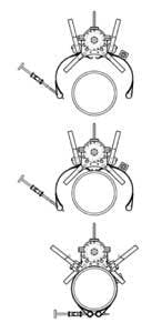
An over-centered, spring-assisted closing device was incorporated to aid positioning and clamping. Spring pressure keeps the clamp in the cocked position, providing the ROV with maximum tolerance on its approach angle. As the clamp device contacts the pipe, the forward load acting on the levers begins closing the clamps. Once the clamps close past the zero position, spring release action takes over, closing the clamps automatically. This applies constant pressure sufficient to hold the sensor system in place.
Using one manipulator to maintain its hold, the ROV checks alignment and then activates the second manipulator to induce circumferential load into the clamp by rotating a bolt to a predetermined torque. Key aspects are the self-aligning bolt and trunnion devices, fabricated from high-strength, low friction materials (Nickel Alloy Bronze and Super Duplex).
The design of all system components takes into account the expected range of movement as a result of the changes in hoop strain due to the pipe’s thermal expansion, internal pressure, and axial loads. Poisson’s effects also must be considered. There must be sufficient tension in the clamp to ensure that it does not loosen at the smallest possible pipe hoop strain. Conversely, all loaded system components must be able to take the loads imposed by the highest pipe hoop strain.
Aspects of performance
Battery power – A rechargeable NiMH battery pack, with a 30-day life span and 100% redundancy, powers the electronics.
Data output – Since changes in hoop strain occur with changes in internal pipe pressure, some effect from axial and thermal movement is expected. The sensor head includes a temperature-sensing FBG, and the housing contains an FSI, a daughter card, the battery pack, a data storage card, and an LED output system for diagnostics and simple load overview. The strain and temperature data are recorded for analysis. For real-time feedback, an ROV-mounted video camera monitors the LED which flashes output data at 15-minute intervals.
Sensitivity and accuracy – Output from the hoop strain sensor is affected by the relative stiffness of the clamp around the circumference of the pipe, therefore a calibration factor is required. In the future this could be exploited further to magnify or moderate the strain signal.
An important advantage of such retrofit systems is the potential for thorough pre-deployment testing and calibration. In the above case, this included a pressure test to 6,000 ft (equivalent) and a functionality test on a similar flowline.
Four such units were successfully deployed in late 2007 and remained on station for 35 days. During this period, the LED outputs were used to monitor ongoing pressure changes. The sensitivity monitored was such that internal pressure changes of 10 psi could be readily detected. All four units were retrieved for full data analysis.
Fatigue analysis on a conductor
Recently, to obtain ongoing fatigue data on a single riser in a shallow water field, a standard curvature monitoring mat was used to measure bending in orthogonal planes. As there was no access to the riser umbilical system, a stand-alone configuration was designed.
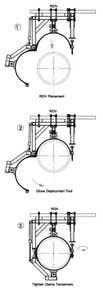
A non-workclass ROV was used for deployment. The ROV’s manipulators were removed and replaced by a separate, built-for-purpose deployment tool, to facilitate installation. The tool consisted of a frame to hold the mat structure and provide all closing and tightening functions, in addition to an emergency disconnect six-function stab plate. The stab plate male end was bolted to the front frame of the ROV. The frame’s hydraulics system was then mated to that of the ROV. The opening and closing operation is depicted in the deployment sequence.
Data from such retrofit installations can be used for design feedback as well as fatigue calculations. This also opens the door for more detailed appraisals when tied to factual, cause-and-effect data – waves, wind currents, vessel movement – and the possibility of extrapolating back fatigue life calculations.
And finally, damaged or failed monitoring devices can be readily changed out or serviced, or have hardware or software updates.
This paper, OMAE 2008-57377, Retrofittable Stress Measurements Instruments for Deepwater Riser and Flowlines, was originally presented at OMAE 2008: 27th International Conference on Offshore Mechanics and Artic Engineering June 15-20, 2008, Estoril, Portugal
About the authors
Damon Roberts is the Schlumberger subsea surveillance engineering advisor. Previously he was with the oil and gas division of Insensys, which was acquired by Schlumberger in 2007. Roberts jointly founded Insensys to develop the commercial application of the strain sensing technology. He has been pioneering the application of the FBG sensing technology since 1995, particularly into practical application, embedding into advanced composite structures, and the development of robust interrogation hardware. Roberts has won many engineering awards associated with this technology and composite design. He has been responsible for the design and build of some of the world’s largest marine carbon composite structures. Roberts received a degree in Mechanical Engineering from Southampton University, UK.
Nuala Murray is the Schlumberger subsea surveillance marketing coordinator. Murray has been working with the technical promotion of this technology into the subsea environment since the first application several years ago.


