Modular J-lay solution has SCR installation ability
System designed for medium-size vessels of opportunity
Didier B. Renard
Coflexip Stena Offshore
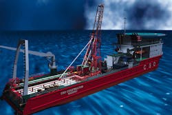
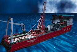
The CSO Constructor is shown in this drawing with the MJ Lay system mounted at midship.A new J-lay system developed by the Offshore Engineering Division of Coflexip Stena Offshore can be deployed worldwide on various medium-sized support vessels of opportunity, and can lay 4-14-in. diameter rigid pipe down to 5000 ft.
The core of the system, known as MJ Lay, consists of a purpose-built modular pipe handling package, automated welding station, and 200-ton pipelay tensioning device suitable for either soft insulation or hard anti-corrosion pipe coating.
The pipelaying process is continuous and advances at a rate of about 1 km/day, depending on size and thickness of pipe. Each joint is welded, tested and coated in the weld station. Buckle arrestors with a local increased wall thickness up to 20mm on diameter can be accommodated without interruption of the lay process as well as flanges up to 26-in. with additional clearance available. Pipeline sleds for diverless connection systems such as Flexconnect can also be fitted to the line as well as pipeline end manifolds (PLEMs) up to 5 meters long by 3 meters by 3 meters, and deployed through the moonpool.
CSO Constructor, a 370-ft-long, 6000-ton dwt dynamically positioned vessel will be the first of Coflexip Stena Offshore's construction class DSV fleet to be equipped this summer with MJ Lay. However, the system's modular packaging means that it can be mobilized at any site worldwide. Thus, costs can be cut on smaller fields and step-out developments by using MJ Lay, rather than calling in a dedicated lay vessel. The easily mobilized system is adaptable to both deepwater and short distance pipelay. MJ Lay kicks off a new generation of customizable and cost-effective pipelay solutions with steel catenary riser (SCR) installation capabilities.
Components
• Onshore fabrication of double-joints: This method requires that an onshore double-jointing facility be set up to fabricate individual lengths of pipe (40 ft in length) into double joints of about 80 ft, which are stored ready for transfer onto the pipelay vessel after they have been fully inspected, field joint coated, internally cleaned, and gauged. The onshore production base with appropriate berthing and load-out facilities will include an area for the initial storage of individual 40 ft pipe joints, pipe ready racks for inspection, alignment racks for line-up, stations for welding, non-destructive testing, and field joint coating of double joints, plus storage racks for the completed joints.•Onboard storage and handling: During load-out, the double joints are placed in heavy duty rack supports onboard the pipelay vessel. When the first MJ Lay operation takes place from CSO Constructor, the pipe strings will be stored longitudinally on the deck between port and starboard cargo rails. The available capacity left for storing double joints on this vessel is about 800 tons.
A transverse beam structure on forward and aft rail supports and equipped with a pipe lifting device (adaptable to single joints or double joints) is used as a pipe string preparation area where, if required, final beveling of the pipe ends is performed with heavy duty pipe facing machines.
Once the double joint is ready, it is transferred to the centerline catwalk and upended for loading into the J-lay derrick. During this transfer, the pipe string is secured on both ends by a set of clamps locking onto the coating free area of the pipe. The clamps are on the lower and upper trolleys running along guide rails. The upper trolley is pulled by two winches located in the mast structure, while the lower one is pushed and/or controlled by a winch capable of holding the load of a double joint in case of failure of the two mast winches.
•J-lay derrick: The J-lay derrick, designed to be installed over the moonpool of the support vessel where its motions are significantly reduced compared to stern or over the side departure locations, is the heart of the MJ Lay. From top to bottom it includes the pipe string support mast, the offshore assembly station, and the pipe tensioning equipment. Those main elements are supported by a heavy duty support structure, which constitutes the base of the J-lay derrick on a grillage around the moonpool.
•Pipe string support mast: A hinged arrangement allows pipeline departure angles of 60-90! from horizontal. The pipe string support mast holds the mast tong and provides the guiding system for the upper trolley.
•Offshore assembly station: This is a fully enclosed working area where all pipe jointing operations - alignment, pre-heat, and welding - are performed. NDT and FJC are also completed in this single station, which provides both environmental protection to the workforce and suitable conditions to perform welding of the required quality.
•Jointing operations: Equipment and tools for these operations are based on existing design. Alignment is achieved by an internal line-up clamp with copper backing shoe; preheat by induction coils, and the automated welding process - pulsed gas metal arc welding (PGMAW) - by pre-programmed computer controlled bugs traveling around a band and remotely controlled by an operator with a hand-held control box. For pipe diameters less of less than 8-in., the SMAW process shall be used.
•Non-destructive testing: The automated ultrasonic method has been selected. It consists of a shoe with an array of built-in ultrasonic probes which scans the full weld in a single pass while traveling on a band around it. UT data is transferred to an onboard computer, displayed on a screen for immediate interpretation, and stored on a CD-ROM. Forced cooling by water will be carried out to bring the pipe surface temperature within the working temperature range of the UT probes.
•Field joint coating: This process varies with the specific pipe coatings and may include surface preparation by vacuum grit-blast, pre-heat, and application of shrink sleeves.
•Pipe tensioning equipment: The unit has a 200-ton maximum pipelay tension capacity and is based on the principle of a "hand over hand" system with a 6-meter maximum stroke between one upper mobile clamp and a lower static clamp. The unit's overall lay speed is 10 m/mn. A double joint requires four "travels" to be lowered after the jointing operations.
To ensure a smooth and easy passage of buckle arrestors and anodes, to guarantee pipeline and field joint coatings integrity during lowering operations, in addition to centering the pipe catenary prior to closing the clamp, two guides above and below the static clamps are provided. A set of adjustable inserts in the lower clamp suit pipe diameters up to 20-in.(e.g. insulated 14-in. pipe).
•Pipeline tension and displacement monitoring: Monitoring of the pipelay parameters will be performed by means of an infrared network linked to a computer.
•Abandon and recovery system: A 200-ton capacity A/R system with 90 mm wire rated for 500 tons MBL completes the MJ Lay pipelaying spread.
Reference:
Coutarel, A., deSoras, D., Sequin, B., Offshore Technology Conference, OTC 8713, 1998.Copyright 1998 Oil & Gas Journal. All Rights Reserved.

