Internal plastic-coated tubing on Coulomb yields 15% increase in daily production
I.A Ituah, L. Stockwell, C.D Stair, R. Kumar - Shell
Steve Neeld -FMC Energy Services Inc.
R. Lauer - Tuboscope NOV
Shell has applied internal plastic coating to the bore of the production tubing for the Coulomb well, providing a more uniform surface thereby lowering the frictional pressure drop in the tubing and contributing to higher production rates from the well.
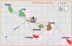
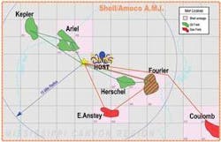
The Coulomb field is the sixth field of the Gulf of Mexico ultra deepwaterNa Kika subsea development. In 7,570 ft (2,307 m) of water, the field covers two leases, Mississippi block 613 (66.7% Shell, 33.3% Petrobras) and Mississippi Canyon block 657 (100% Shell), which consists of a single reservoir structurally separated into two accumulations.
The wells were drilled using the Transocean’sDeepwater Nautilus rig. This included a re-entry of the original MC 657 well in the southern block (C-2) and the appraisal drilling and completion into the northern MC 613 block (C-3).
Internal coating selection
It has been concluded that the energy loss caused by surface roughness varies with the square of the system velocity. This indicates that in tubing, at high velocities, surface roughness becomes an increasing important factor affecting turbulence. The more uniform surface improves flow dynamics to help maximize productivity by lowering of frictional pressure drop.
Shell considered three internal coating candidates: a liquid applied modified phenolic, a powder applied epoxy novolac, and a powder applied modified epoxy. The liquid applied modified phenolic is qualified by Shell as a tubular coating for certain gas well applications. It possesses a unique chemical make-up that allows it to achieve good decompression resistance.
Surface roughness ranges from 8-11 micron and the entire coating thickness is between 5-8 mils (127-203 microns). The powder applied epoxy novolac is marketed primarily in Europe both for oil and gas wells. The surface roughness is 1.4-2.8 microns while the entire coating thickness ranges from 7-15 mils (178-381 microns).
The powder-applied modified epoxy has characteristics similar to the epoxy novolac with a liquid phenolic as the primer and a powder as the topcoat. It is also a candidate for oil and gas wells. This modified epoxy has a surface roughness between 1-3 microns and a thickness between 8-13 mils (203-330 microns).
Seven test methods were selected to evaluate the coating performance of both coating systems: autoclave and, chemical immersion, sand control, wet adhesion, surface roughness, and flexure strain. The autoclave and chemical immersion test were conducted by Tuboscope, while the sand control fluids tests were conducted by Halliburton.
Three further measurements were made to assess their performance:
- Wet adhesion for degradation of adhesion or durability
- Roughness for degradation of surface smoothness
- Flexure strain for the age stability of the coating material after thermal degradation and chemical immersion.
The thermal results of both coatings were good. However, both powder coatings were shown to have weaknesses in mechanical properties. Results of the test concluded that the modified epoxy met the necessary requirements to withstand the well environment.
Coatings specifications
Due to the relatively short track record of the modified epoxy coating in subsea wells and the laboratory determining apparent mechanical weakness, the coating application specification was modified such that the maximum thickness was set at 10 mils (254 microns). This was in addition to increasing overall quality control.
Additional stipulations were detailed to address well specific needs at different stages of the coating process:
- The coating was specified to be 5-10 mils (127-254 microns) in thickness
- All tubing joints were coated with the modified epoxy coating and the pup joints were coated with the liquid applied modified phenolic
- All coated components were stenciled with specific manufacturer’s alloy identity and standard codes
- Dry film thickness (DFT) measurement for the first 10 joints at 12-3-6-9 clock positions and one position on every seventh joint thereafter
- Infrared scan was performed on the base material prior to application, as well as visual inspection on all joints thereafter
- Additional visual inspection during buck-on, dock loading, and installation on the rig
- Reject classification - pipe with more than 4 holidays and coating thickness outside the set range of 5-10 mils (127-254 microns).
Mitigation against damage
As indicated in the test results of both coatings, the weak impact resistance was a potential drawback. Procedures described by NACE standard RP0291-96, item No. 21049 on care, handling, and installing of internally coated tubulars were followed. As much as practically possible, wireline runs were eliminated.
Normal operations call for two wireline runs, the first sets the production packer and the second sets a plug in the tubing hanger to act as second barrier prior to removing the subsea BOP. Purposely, the use of a remotely opened isolation valve in both instances fulfilled both objectives and eliminated the need for wireline runs.
Prior verifications were performed on the flexure strain on the internal coating the stress-strain curve for 115 ksi material applies to 110 ksi material as well. It shows 0.5% strain value at the yield of the pipe material. Therefore, the 0.69% strain value quoted for the powder applied modified epoxy was beyond the pipe yield value. The pipe does indeed yield before the coating would fail by de-bonding. This was the last remaining obstacle to running the double stands.
Nodal analysis demonstrated that the reduced tubing friction associated with the use of internal plastic coating in the tubing would yield a 15% increase in daily production in these wells.
Project challenges
Reservoir uncertainties such as compartmentalization, aquifer size, fluid compatibility and proximity, and connectivity between the reservoirs made it necessary to design a development plan providing maximum flexibility in the drill-complete sequence. Previous penetrations in the southern block encountered a hybrid sand consisting of a basal massive, high net/gross sand overlain by a thinning upward laminated sequence. The primary reservoir target was the BS50 but a possible additional pay sequence directly below was identified by subsurface as an additional target. Through a decision tree analysis, a 20% possibility that at least one of the two Coulomb wells would encounter the additional and deeper gas zone was estimated. The desire for a quick turn around on a wildcat resulted in stringent project management and contingency planning practices.
The completions were designed:
- To take full account of safety, technical integrity, and operability during installation and production
- To accommodate risk of reservoir compaction with depletion
- To take full advantage of common casing sizes and simplify completion design by standardizing equipment.
Completion execution
The Coulomb wells were completed in a fairly conventional manner. The wells were cleaned out on a single trip, perforated using tubing conveyed guns, and sand control placement was performed using the frac packing method. The single production tubing was run with a permanent downhole temperature pressure gauge and a tubing retrievable subsurface safety valve.
The tubing was hung off with a metal-to-metal seals concentric bore tubing hanger. However, when completing wells in 7,600 ft (2,316 m) of water, on a rig that has not done any completion operations, even the conventional looking completions pose quite a few challenges.
The wells were completed with 4 1/2-in. (114 mm) 13 Cr 110 tubing with premium-threaded connections including Teflon seal rings (VAM ACE RS Type 1). The tubing design was driven by load conditions including tubing evacuation (collapse scenario), and start cold kill (burst scenario). Internal plastic coating was applied to the bore of the tubing for improved hydraulic efficiency, resulting in a 15% improvement on production rate.
On the first well, running the production string in doubles was experimented. On the C-3 well, all of the production tubing was run in doubles, time reduction was about 50%. It proved to be time saving.
The flat pack and TEC were terminated beneath the tubing hanger and tested; pressure was maintained on the flatpack to keep the flapper on the SCSSV opened. The downhole gauge was constantly monitored at the surface during installation. Cross collar protectors were installed on every joint from the downhole gauge to the tubing hanger to minimize damage during the tubing installation.
The surface-controlled subsurface safety valve (SCSSV) is 4 1/2-in. (114 mm), 10 ksi rated. The depth of installation is 10,660 ft (3,249 m). Safety clamps were used to secure the umbilical to the 5 1⁄2-in. (140 mm) drillpipe riser while the production tubing assembly was lowered through the riser to tubing head spool on the mudline.
Commissioning
Commissioning the wells included opening the well barriers remotely, expending the remaining fluid loss device, unloading the completion brine in the production tubing, cleaning up of the well fluid, and dosing the tree and wellhead with methanol for hydrate mitigation. The C-2 well achieved a maximum rate of 95 MMcf/d gas, 25% above expectations. The C-3 well has performed as anticipated thus far at a rate of 45 MMcf/d. The two completions were finished in less than a full month (30 days actual as against 50 days planned). The wells came in 23% below AFE cost. The excellent performance in these wells is a contribution of many factors:
- Dedicated completion design and execution team
- Highly skilled and motivated rig crew and service personnel
- Continuous improvement process designed to capture learning and efficiencies
- Adopting best practices from deepwater projects.
Editor’s Note: This is a summary of SPE 102963 paper prepared for presentation at the 2006 SPE Annual Technical Conference and Exhibition held in San Antonio, Texas, U.S.A., Sept. 24-27, 2006.


