Low shear valve simplifies separator debottlenecking
Flow control technology tested offshore Norway
Niels van Teeffelen,Typhonix AS
Rune Husveg,Typhonix AS
Robert Verwey,Mokveld Valves BV
Conventional choke and controlvalves are known to mix and emulsify the petroleum phases, leading to downstream separation problems. Emulsification and droplet breakup are results of high shear forces in the throttling valves. Typhonix AS, in close cooperation with Mokveld Valves BV, has developed a low shear flow control system to optimize and debottleneck separators.
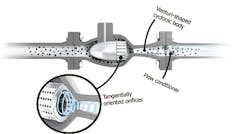
The Typhoon Valve System is a cyclone-based valve concept, using the principles of a vortex to control the flow rate and pressure of a fluid. The internals include 1) a cage with tangentially oriented orifices to regulate and transform an axial inlet flow into a vortex flow, 2) a venturi-shaped cyclonic body optimized to develop a suitable vortex pressure drop and 3) a flow conditioner which transom the vortex flow back to an axial outlet flow. The swirling flow within the system reduces shear forces and the level of turbulence, and the consequence is that the controlled fluid phases are less mixed and emulsified.
Focusing on oil-water separation, the technology can advantageously replace valves located upstream of the main separation equipment or produced water treatment equipment, e.g., upstream large three-phase separators, hydrocyclones, degassers, and flotation units.
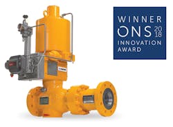
The Typhoon Valve System won the Innovation Award at ONS 2018.
Depending on the application, benefits of debottlenecking with the low shear system are:
• Improved oil and water quality
• Cost-efficient separation system enhancement
• Increased separator capacity
• More compact separation systems
• Longer economic production life of high water cut wells
• Reduced need for separation enhancing production chemicals
• Less need for heating.
Field results
This technology has, through several years of experimental investigations, documented a significant positive effect on downstream separation, improving oil and water quality. Results from trials and field installations show performance improvement across a wide range of process conditions and fluid compositions.
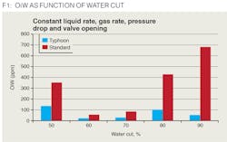
The separation benefit of the system was first documented at realistic test conditions in Equinor’s multi-phase flow loop in Porsgrunn, Norway, in 2009. Medium crude oil from the Gullfaks field was used together with natural gas and salt water. Replacing the conventional multi-stage valve with the Typhoon Valve System, systematically reduced the oil content in the water downstream of the separator by 60-90%, and the water in oil by an average 25%.
Illustration of the Typhoon Valve System internals.
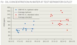
For the offshore trial, the system was installed on Oseberg C, an Equinor-operated production facility in the North Sea. Here, the oil content in the water from the test separator was systematically reduced by more than 45%, on average, and the water in oil content was on average reduced by 35%.
For an offshore test campaign, the system was installed on the Fram West flowline on the Troll C platform. Here, it systematically reduced the average oil in water content by 60% compared to the single-stage conventional choke valve for this installation.
Reduction of oil in the produced water after installing the technology.
Separator debottlenecking
Due to million years of retention time, oil and water have formed separate layers in the reservoir. Unfortunately, during production, the phases are mixed. Mixing of these naturally immiscible liquids causes an oil-water emulsion. In the production systems, liquid mixing is mainly caused by the choke valves, control valves, and pumps. The higher the intensity of the mixing, the tighter the emulsion becomes, forming micron-sized droplets of oil in the water and water in oil. Tighter and more stable emulsions are harder to separate and therefore require an elaborate separation system in addition to the use of chemicals and heat to separate the liquids.
Quality specifications for the export oil and produced water set the requirements for the design of the separation system. Based on pre-estimated production profiles, the separation system is designed to meet said quality criteria over the lifetime of the field.In reality, the well performance deviates from the pre-estimated profiles, and the operating conditions may exceed the design envelope of the separator. When this occurs, the level of impurity of the separated phases becomes a bottleneck. Expensive and elaborate modifications are normally required to restore the production rates to its required quality. Several possible solutions are available, mainly focusing on increasing the bulk separation capacity or improving the downstream treatment systems to handle the reduced product quality from the bulk separation system.
Conventional separator performance upgrades require extensive modifications. Available options depend on the field’s location (offshore or onshore) as well as the field’s economy. Installation of a larger separator or a parallel vessel is one of the options, which, apart from the economics, may be technically feasible onshore, but is very unlikely to be feasible offshore due to space limitations. Other options are retrofitting the separator internals to provide better separation efficiency or to add compact pre-separation equipment upstream of the separator.
In cases where the amount of water remaining in the oil (WiO) or the amount of oil remaining in the water (OiW) after separation limits the throughput of the separator, the low shear system can be used as an effective debottlenecking solution.
Separation of the fluids in traditional gravity separators strongly depends on the dispersed phase droplet sizes (as shown by Stoke’s Law). The larger the droplets, the more efficient the separation. The separation efficiency of a gravity separator therefore strongly depends on the droplet size distribution and the degree of emulsification of the fluids entering the separator. This system, being a low shear flow control technology, reduces droplet break-up and fluid emulsification upstream of the gravity separator in comparison to conventional valve technologies.
By improving the separability of the feed stream, by reducing droplet break-up and emulsification, the separator throughput can be increased.The graph in F3 shows the separator retention time as a function of the water quality on the separator outlet. It is seen that a specific water quality is reached at a much shorter separation time when the low shear system is used upstream of the separator, compared to that of the conventional valve.
One of the benefits of the low shear approach is that it does not require any modifications to the separator itself or the installation of any new additional equipment upstream. Replacement of the standard choke or control valve with the low shear system is, therefore, a very cost-efficient way to debottleneck the separation system and free additional capacity.
Droplet settling and separator capacity
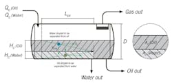
The droplet settling theory, being one of the primary techniques used for the sizing of gravity separators, can be employed to quantify the separator capacity increase enabled by the installation of a low shear valve. The droplet settling theory was developed to estimate the separator volume and dimensions necessary to separate the droplets of the dispersed phase above certain droplet diameter (cut-off diameter) at a given flow rate. The theory is based on the settling law expression, such as Stoke’s Law. For visual simplicity of the theory, the flow in a weir separator is considered.
After the feed stream enters the separator, gas, oil and water layers are established within the vessel. While fluids are flowing horizontally through the gravity separation section toward the outlets, dispersed droplets have a chance to rise to the oil-water interface. Based on the retention time, which is determined by the flow rate and the height of the oil/water layer, the minimal droplet size that can be separated can be determined.Case study: brownfield
For brownfield applications, the separator size is already determined. Installing low shear valves upstream of the separator will increase the size of the droplets entering the separator, and thereby increase the separation efficiency. Use of low shear valves in this position will, therefore, reduce the water-in-oil and oil-in-water content of the streams leaving the separator for the existing production rates. In cases where it is sufficient with conventional valves, low shear valves can be used to increase the separators capacity. Larger droplets separate more quickly, enabling a higher liquid flow rate through the separator without changing the separator outlet oil and water qualities. This is also valid for cases where production is restricted due to underperforming separators caused by shear in valves upstream of the separator.
To quantify the effect of using a low shear valve, a conservative average droplet size increase of 10% to 15% is used in the case study to evaluate the result on the separator capacity. Based on the field test results presented earlier, this is a realistic assumption. Furthermore, to quantify the effect of the larger droplets when using a low shear Typhoon Valve System, the droplet settling theory can be used. Because of the increased efficiency of the separator, a larger droplet cut-off diameter can be used while still maintaining the oil and water quality as before. For a given vessel, the increase in cut-off droplet diameter reduces the required retention time, in other words, the production rate can be increased. A 10 to 15% increase in the cut-off droplet size due to use of this system, will enable approximately 20 to 30% increase in production flow rate for a constant oil and water qualities on the separator outlet.
Settling trajectories of dispersed oil and water droplets that would have 100% removal efficiency.
Case study: greenfield
Including this system in the process plant design from the planning phase will help to optimize the separation system and prevent (or significantly reduce) the formation of tight emulsions. A thorough evaluation of the capacity constraints can result in more compact separators necessary to satisfy the design parameters with regards to the separation efficiency required. The droplet settling theory can be successfully applied for the sizing of the separator with regards to liquid carry over to gas phase, as well as oil and water carry over to the corresponding produced water and bulk oil streams.
Without available droplet size information, it is common to choose a recommended cut-off diameter size for separator sizing. When using the same conservative assumption of this system’s average droplet sizes increase of 10-15%, the effect on the required separator size can be evaluated. The 10 to 15% increase in the droplet cut-off size when using the system results in an approximately 15 to 25% reduction of the effective liquid separation volume required.
Conclusion
Reduction of shear forces acting on the fluids upstream of separation trains by use of low shear flow control technology, like the Typhoon Valve System, minimizes droplet breakup and the formation of tight emulsions, thereby improving separation and increasing separation capacity.
The system can also be used to increase the separator efficiency instead of increasing its capacity. This approach is particularly useful when there are problems due to tight emulsions. Additional benefits could be a reduced requirement for separation enhancing production chemicals like demulsifiers and reduced heating of the liquids.
Implementation of the low shear flow control technology is a simple and efficient solution for debottlenecking the liquid capacity of a three-phase gravity separator. The system retrofit does not require any modification to the separator itself. In most of the cases, it can simply replace existing choke or control valves. •

