Flare-less requirements drive innovation on the Okha FPSO
Marten Akesson
Nicolas Bigle
Arjan Gerritse
SBM Offshore
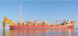
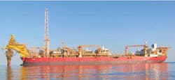
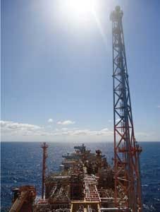
In 2009, Australia's Woodside Energy awarded SBM Offshore an engineering, procurement, and construction contract to deliver a disconnectable FPSO to serve the Cossack, Wanaea, Lambert, and Hermes fields offshore Western Australia. Dubbed theOkha and moored in 80-m (262-ft) water depths, the FPSO went onstream in September 2011, as part of the AU1.8-billion ($1.88-billion) CWLH Redevelopment Project.
Initially considered to reduce corrosion rates in the cargo tanks of the converted vessel, hydrocarbon tank blanketing, which would replace the conventional inert gas cargo tank blanketing, was soon seen as an opportunity to reduce the FPSO's emissions and overall environmental impact. When combined with recovery of low-pressure (LP) flare system releases and a closed high-pressure (HP) flare system, flare purge gas combustion could be avoided, resulting in an FPSO with zero hydrocarbon/CO2 release to the atmosphere.
Yet the design of such a novel system had significant challenges such as managing all HP/LP interfaces, selecting the appropriate vapor recovery unit (VRU), and simultaneous control of HP flare, LP flare and cargo vent operating pressure for all operating cases, including offloading. This required that conventional systems be revisited through an in-depth analysis to ensure that changes associated with the new configuration were properly managed and did not generate additional operational risk.
The complete VRU system, at normal capacity, is able to recover and re-inject around 4 MMcf/d of gas that would normally be lost to the atmosphere, and allows the FPSO to produce without flaring, except in emergencies.
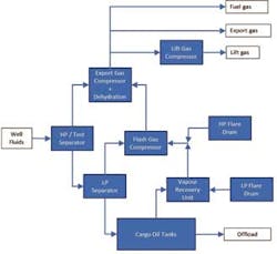
The design basis specified that fuel gas was to be used for cargo tank blanketing, in line with Australian regulatory requirements, which meant that it became necessary to implement a totally enclosed flare system collecting all continuous hydrocarbon releases – a first for SBM and for Australian production facilities. The principle of this system is simple: all LP hydrocarbon gases released from the process plant are sent to the LP flare header and, after liquid removal in the LP flare drum, sent to the VRUs for compression. Gasses from the cargo tanks and the produced water tanks are routed directly to the suction of the VRU. The same is done for the HP hydrocarbon gases released from the process plant to the HP flare headers, which, after liquid removal in the HP flare drum, are sent to a centrifugal flash gas compressor and mixed with other gas. Recovered gases are either used as fuel gas, for gas lift (to boost crude production), or exported to shore. The key new components of this zero flaring system are:
- A hydrocarbon main piping system connecting all cargo and produced water tanks
- Two 100% vapor recovery units
- Quick-opening shutdown valves downstream of the HP and LP flare drums
- Rupture pin pressure safety valves in parallel to the quick opening shutdown valves
- A flare tip ignition system using sparks of an air-driven pellet.
TheOkha FPSO is designed with two-stage crude separation on the topsides (high and low pressure) and a third and final separation stage in any one of the cargo oil tanks (COTs). Produced water goes overboard after passing through hydrocyclones and a flash vessel. Gas is exported primarily via an export gas header to the Karratha gas plant and partly used for lift-gas to the wells, and fuel gas for the gas turbine generators.
Gas from the HP separator is compressed in a two-stage export gas compressor (EGC) with interstage gas dehydration. Gas from the EGC is routed to the lift gas compressor (LGC) and export gas header. Both the EGC and LGC are centrifugal compressors with Voith variable speed gear couplings driven by electric motors.
Gas from the LP separator is compressed in the flash gas compressor (FGC), a two-stage fixed-speed centrifugal compressor, and fed to the suction of the EGC. Gas flashed from the crude run-down in the COTs is fed to the VRU.
Marine system
A hydrocarbon gas header was added to the marine system to maintain the separation between the inert gas and hydrocarbon systems. As theOkha is a conversion, the main challenge of this is routing the header through the already constricted space on the main deck.
Flare recycle system
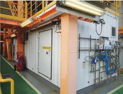
The VRU is a single-stage roots blower, compressing boil-off gas from the COTs as well as gas from the LP flare drum. For noise control, the VRUs were located in acoustic enclosures.
The FGC is a two-stage fixed-speed centrifugal compressor, compressing gas from the LP separator as well as the VRU and HP flare drum.
A number of changes to the flare system were required to create a flare-less unit. Upstream of the flare drum, the system is only changed in that the LP and HP flare headers and flare drums are pressurized, which increases the back-pressure on pressure safety valves (PSVs). This potentially impacts PSV selection, but for theOkha did not result in additional requirements for the relief devices.
A minor effect is that normal back pressure increases on all process units that usually are open to atmosphere, e.g. the produced water flash vessel and the glycol regeneration package still column, where the increased pressure marginally reduces the efficiency of the regeneration system.
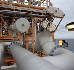
The discharge from the flare drum to the flare tip has two valves in parallel. The primary pressure relief is a fast opening valve. The second, a rupture pin valve, provides a secondary mechanical relief device should the fast opening valve fail to open.
A rupture pin valve was chosen over a rupture disc because it allows the valve to be reset without requiring the valve to be isolated from the process, significantly simplifying the design. Being external to the process, the pin is also not subject to corrosion from the process gas.
To prevent liquid sitting on the fast opening valve and rupture pin valve, piping design required a dead-leg at a low point in the flare drum discharge piping. Liquid accumulation during flaring introduces the potential for liquid carry-over, something not seen in conventional flaring designs, where any condensate drains back into the flare drum.
Ignition
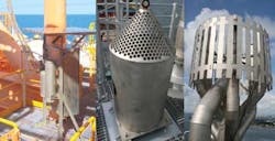
Rather than maintaining a pilot flame, a pellet type flare ignition system is used. An exploding pellet is launched with instrument air through a guide pipe to ignite the flare. To guarantee ignition, two pellets are launched on every incident. The system is equipped with two air accumulators to ensure that the flare can be ignited in case of instrument air loss. Ignition is initiated automatically on the opening of either the fast opening valve or the rupture pin valve.
The pellet is armed on launch and ignites on leaving the guide pipe to the flare tip, while the pellet is caught in a fragment collector. One challenge during construction was to ensure that the guide pipe ran without any kinks to allow the pellet free travel to the flare tip and to minimize the possibility of a pellet sticking inside the guide pipe. The final ignition initiator is by spring-loaded wings popping out of the pellet as it leaves the guide pipe, ensuring that the pellet does not ignite before leaving the tube. A stuck pellet would be difficult to locate and to remove safely from the guide pipe.
The pellet launcher requires manual reloading of the pellet magazine. An alarm alerts the operator when the magazine is half-full.
The case of a flare failing to ignite was studied and it was concluded that in the worst case, the gas would disperse before reaching the deck. A secondary ignition system therefore was not required. As the system uses instrument air, failure of the air system would potentially cause a blow-down without the possibility of flare ignition. So, the system was equipped with two air reservoirs. Should the air pressure drop below the minimum required to send the pellet to the flare tip, the launch sequence is stopped. Integrity of this system relies on the sealing quality of one non-return valve (NRV) and has been proven on numerous North Sea facilities. Debris was found to obstruct the NRV on one launch but it has since proved reliable.
Operating envelope
The VRU has been operating from 0% to 100%. The low end is during offloads, when gas is diverted from the LP separator to the COTs to maintain pressure. Normal load is gas from production boil-off, relatively low flows from the TEG regeneration stripping column and the flare header fuel gas purges. Periodic increases in the load occur when loading of empty cargo tanks begins due to vapor disengagement on account of the fall height from inlet to the bottom of the COTs, and when hot produced water is routed inboard.
A number of solutions were proposed to deal with the challenge of designing for very low turndown. Among the proposals were 4 x 33% units, variable speed drives (VSD), water quench, and full recycle. In the end, the selected VRU design was 100% recycle and equipped with VSD (although these were primarily for frequency conversion). In actual operation, the VSDs are extremely useful for optimizing the operation of the VRU.
Offloading operations have less effect on the FGC as the main feed to the unit is from the LP separator. However, the entire compression train is affected by turndown, because the VRU adds a high molecular weight (MW) feed to the gas.
Rather than distributing oil along the bottom of the tank, the feed is to a splash plate above normal liquid level, ensuring that there is sufficient liquid/gas separation in the tanks to achieve the RVP (Reid's vapor pressure) offload specification. This has two effects: increases turbulence, making the level measurement in the tanks to which rundown is being directed slightly less accurate; and a fall height during initial loading that increases the amount of boil-off gas generated, causing a temporary spike in COT pressure and increasing the duty on the VRU until the system stabilizes.
The VRU must cope with a wide range of molecular weights. During normal tank loading operations, MW was modeled at 52 g/mol, down to 30 g/mol after offloading, when the cargo tanks have been fed with gas from the LP separator. This has a considerable impact on the main gas compressor trains, increasing efficiency as higher molecular weight gas is received from the VRU and FGC, but also increasing the amount of liquid knocked out in the drums. Tolerance for high variations in molecular weight and robustness were key factors in selecting the root blower for the VRU.
The only continuous sources to the HP flare drum are the HP and cold flare header fuel gas purges. Operations teams observed that the closed flare system made it easy to note when valves were either passing or left in open positions, as pressure in the flare drums would increase to push the extra gas through to the VRU or FGC.
Commissioning
After the usual pre-commissioning activities, including blower/motor alignment and instruments loop checks, the cause and effect logic were tested to ensure the VRUs would react as required in case of problems and were safe to run. The next step was to run the VRU on full recycle with a nitrogen/helium mix to confirm that the unit had not been damaged during transport/installation, and worked as required with connected utility systems. Calibration of all sensors – mainly vibration sensors – was confirmed by external measurements. However, due to the limited cooling medium capacity in the yard, the system could not be run in full recycle for a long period. As the system was designed to work with a wide span of inlet gas, the VRUs were tested in open loop, sucking air from cargo tanks and injecting it into LP flare system. This provided temperature equalization within the unit to ensure stable operation in normal conditions.
This first batch of tests done onshore gave a good overview of how the system operates and what parameters could be used to tune the system. An electrical frequency converter was installed upstream of the main motor, which was used as a variable speed drive to avoid critical blower speed frequencies. Operations were later optimized for the lower through-put.
A loading philosophy for the VRU was developed, based on the operating experience while running the unit on air in the yard, to ensure that critical speeds are not achieved in the blower. This required further optimization during hydrocarbon commissioning, but the baseline achieved during pre-commissioning significantly simplified later work.
One limitation of testing with air is that the system does not experience the same condensation as it does with water-saturated hydrocarbons. Hydrocarbon test runs conducted after the onshore commissioning suggested that the package was oversized, and that condensed water from the inlet gas mixture generated excessive vibrations in the system. This led to further work offshore, including modifications to the cooling system to prevent over-cooling of the gas.
Operations
During normal operations, the fast opening valves on the flare drum discharges are closed and the paths to the VRU and FGC are opened. Pressure then begins to build in the flare drums until there is sufficient pressure to flow gas to the compressors.
Introducing boil-off gas from the COTs to the compression train was found to increase the formation of liquids in the main export gas compressor's liquid knock-out drums and to decrease duty on the compressor as the molecular weight of the gas increased. During operations with low gas loads, this resulted in much higher liquid formation than expected.
Operation of the FGC has been stable, coping well with valve leakages and high gas flow from the GTG fuel gas warm-up lines. Operating experience reiterated the need to step through changes slowly and to allow the system to settle as a whole. Once throughput was established, the system was found to operate smoothly as a whole.
Normally oil rundown is distributed along the bottom of the cargo tanks so as not to disturb the liquid and to ensure optimal level measurement in the tanks. Because the final stage of separation takes place in the COTs, the rundown to the tanks is at the top of the tanks. When marine operations change to loading an empty tank, the extra fall height results in increased vapor disengagement, which briefly increases the load on the VRU.
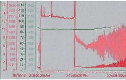
With the flare running, a significant amount of liquids condense in the flare stack itself due to wind and ambient temperatures below that of the flare gas. Essentially, the flare stack becomes a very long air-cooler with a temperature differential of up to 20°C (68ºF) depending on run-down temperature, ambient temperature, and operations. This resulted in liquid formation of up to 25 liters per hour (6.6 gal/hr). Had the unit been designed to flare continuously, this would have drained back into the flare drum. However, as the flare system was designed to have a low point between the drum and the flare stack to prevent rain water from sitting against the fast opening valve, this liquid collects in the dead leg. When full, it is noted by flow and pressure fluctuating as liquid sloshes back and forth with vessel motion. The chart shows the fluctuation in flow (pink) and pressure (red) as liquid filling the dead leg begins to impact the flow and pressure in the flare drum outlet.
The main concern of this is that if there is an incident soon after flare-less operations are restarted, but before operations teams have had time to drain the flare header, then liquids that have been suspended in the stack by the gas velocity can be pushed out onto the deck. Because the flare stack operates more or less like an inefficient distillation column, the liquid is water with some dissolved heavy hydrocarbons and there is no risk of the liquid igniting.
Over-cooling of the discharge gas from the VRU caused liquid build-up in the spare VRU due to pipework configuration at the outlet of both VRUs. The unit was equipped with a manual globe valve, but because of high differential pressure this did not provide sufficient control. The addition of restriction orifices to increase the back pressure improved operations, but the units continued to experience liquid build-up. A temperature control valve was installed on one of the VRUs and both units ran successfully. Installation of the same arrangement on the second unit is pending.
Use of tubing was found to exacerbate vibrations during operation, causing failure of small-bore lube oil and nitrogen lines. Decoupling these by installing small flexible hoses considerably reduced the effects of vibration and failure of the small-bore tubing.
Benefits
Obvious benefits of a closed flare system are increased production and a reduced environmental footprint. The latter has further potential benefits in the form of carbon credits and reduced CO2 taxes.
As the flare tip itself is no longer subject to continuous flaring, wear and tear is significantly reduced. Experience on other units has shown that continuously flaring may require several flare tip changes during the lifetime of the unit; this is now potentially reduced to none. Similarly, the demand on the inert gas system is reduced.
Working conditions on the FPSO improve significantly with flare-less operation, particularly on top of the modules that are closest to the flare stack, where heat fatigue can otherwise be a significant issue in the summer.
Conclusion
In an effort to reduce greenhouse emissions, countries are increasingly imposing regulations that require flare-less oil and gas operations. The main points to consider for an optimal design of a vapor recovery system for an FPSO with hydrocarbon blanketing are:
- Turn-down, from 0% to 100%
- Liquid control during all phases of the operating envelope
- Robustness of design to varying gas composition, and the effect on the main compressor trains
- Potential for sour well fluids
- Effect of back pressure on other processes.
Flare-less operations can be implemented with relative ease if required from the beginning. With drivers that include environmental regulations, emissions reduction, production optimization and improved working conditions, it is expected that flare-less designs will become the new standard for FPSOs and platforms.
Acknowledgment
Based on a paper presented at the Deep Offshore Technology International Conference & Exhibition held Nov. 27-29, 2012, in Perth Australia.
Offshore Articles Archives
View Oil and Gas Articles on PennEnergy.com
