Petrobras’ PROCAP 3000 pursues new deepwater technology
Peter Howard Wertheim, Dayse Abrantes - Contributing Editors
Petrobras’ deepwater technological program (PROCAP 3000) is investigating technologies for exploration and production in 3,000 m (9,842 ft) water depth. The first phase, carried out in 2005, consisted of technical and economical evaluations, resulting in the addition of production-injection wells on the Marlim field. The second and third phases, which are being developed together, comprise a series of lab and field tests on basic subsea system design.
In an exclusive interview withOffshore magazine, Mauricio Werneck de Figueiredo, PROCAP 3000 coordinator, discussed four projects that illustrate how Cenpes, Petrobras’ research and development center, maintains the company’s pioneer position in deepwater exploration.
“To operate in deepwater scenario with the cutting edge of technology requires extensive planning, intensive work, and a lot of creativity to anticipate most of the problems for a high-cost and never -experienced operation,” de Figueiredo says. The Cenpes team follows a conventional routine for most projects, gathering historical data, developing tests, and carrying out simulations to develop solutions to the problems at hand.
Some projects, however, require an extra level of attention, de Figueiredo says, either because of the size of the challenge or the degree of innovation applied.
Subsea installation
One challenge being investigated by Cenpes is subsea installation. Oil production in deepwater requires the installation of a great amount of equipment on the seabed, de Figueiredo says. Installations of relatively small size and low weight can be placed using rig cranes, but others, like subsea manifolds, require special vessels equipped with heavy lift cranes.
Historically, costs related to the mobilization and demobilization of such vessels were prohibitive, due in part to increasing worldwide demand. Another factor for Petrobras is that, until a few years, the company was the only operator offshore Brazil, which means Petrobras had to bear the brunt of expenses alone.
With the expansion of experience since the first diverless manifold was installed on the Albacora field in the Campos basin in 1995, several methods of installation have been used to overcome the lack of available vessels for installation of heavier loads in deeper waters.
Problems associated with this operation are mainly the time required to safely lay a structure weighing more than 200 metric tons (220.5 tons) on the seabed and the possibility of resonance between the movement of the installation vessel and the natural frequency of slender laying cables.
Several simulations in each installation defined the operational window in terms of waves and currents to allow the installation, de Figueiredo explains.
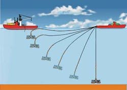
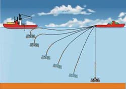
After extensively analyzing this problem, Cenpes came up with an innovative method to reduce time and avoid resonance. The solution was to move the load very quickly from the surface to the final position using a pendulum motion.
The operation is carried out using one boat to hang the manifold, attached by a launching cable, just below the sea surface. A second boat is positioned at the other end of the cable, just above the subsea target where the manifold is to be positioned. The distance between the two vessels should be about 100 m (330 ft) less than the water depth.
The vessel suspending the manifold releases it. The manifold falls through the water, eventually coming to rest 100 m (328 ft) above the installation point. When the manifold stabilizes, the second boat finishes the installation.
Cenpes carried out a great number of numeric simulations and small scale (1:35) model simulations, de Figueiredo says. The group also carried out a monitored installation test of a real-scale model manifold using the same barge and boat that would be used for the actual installation.
The test was monitored by accelerometers registering the movements of the model manifold during the fall from the point where it was released from the first vessel until it reached its final target. Data analysis allowed the method to be calibrated so that installation procedures could be developed.
By year-end 2006, two gas lift manifolds had been installed using this technique on the Roncador field in the Campos basin. Manifold MSGL-RO3, weighing 280 metric tons (308.6 tons) was installed in 1,845 m (6,053 ft) water depth, and manifold MSGL-RO2, weighing 230 metric tons (253.5 tons), was installed in 1,882 m (6,175 ft) water depth.
Both manifolds were installed within a 5-m (16-ft) target circle with a heading within five degrees tolerance. The placement for both manifolds was carried out in approximately five days.
Riser fatigue
Risers work under a very complex system of loads, including current, weight, and waves. Each of these loads imposes a different effect on the structure and must be correctly accounted for when calculating the fatigue life of the riser. The deeper the production units, the more complex the problem.
Petrobras is working on two approaches to extend the life of risers. One approach is to design hulls that are steadier even under very severe current and wave loads. This would reduce loads on the riser and mooring systems, de Figueiredo says. A second approach is to use a subsurface floating device to hold the riser and to attach it to the unit by flexible loops, isolating the movement of the riser from the unit.
The surface riser buoy (SRB) is a square tubular structure formed by cylinders positioned 100 m (328 ft) below sea level by means of vertical tendons. The cylinders are moored by cable and are anchored on the seabed by torpedo piles.
From the wells and manifolds, steel catenary risers hang on the buoy attached to the flexible jumpers that cross the buoy and connect to the production unit.
A project using this concept was developed for the east board of theP-52 semisubmersible platform on the Roncador field. The buoy center was placed 430 m (1,411 ft) away from the center of the platform in 1,800 m (5,906 ft) water depth. The buoy was positioned 100 m (328 ft) below the sea level, which avoided the influence of the waves.
The buoy was 40 m x 47 m (131 ft x 154 ft), formed by 5-m (16 ft) outside diameter cylinders on three sides and a 12.5-m (41-ft) cylinder on the side where the steel risers hang off. The system was designed for 19 seven-inch and eight-inch risers. The total weight was 1,500 metric tons (1,653.5 tons), and the buoyancy was 8,000 metric tons (8,818.5 tons).
Positioning the buoy using eight tendons, two at each corner, provided redundancy in case of failure. Simulations were carried out on the system for different sea conditions and for a one-line mooring failure. The tests demonstrated the structure’s stability even with high movement intensity of the production unit. The concept was not adopted forP-52, as the use of free catenary risers is still possible there at a lower cost.
To prove the feasibility of the configuration and to develop all procedures for towing, installation, and recovery of the buoy, a test will be performed, using a 27 m x 27 m (89 ft x 89 ft) buoy with 2.5-m (8-ft) outside diameter cylinders, with the risers positioned one on top of the other.
The test is planned for August 2008, in 500 m (1,640 ft) water depth using two risers. The buoy, risers, and environmental conditions will be fully monitored at each phase of the six-month test, de Figueiredo says.
Working with hybrids
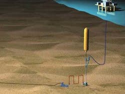
Another riser system under development uses the same concept of separating the movements of the production unit from the risers. The basic concept is to use a rigid large-bore vertical riser with the bottom mechanically connected to a fixed base on the mudline, hydraulically connected to the pipeline and sustained on top by a cylindrical vertical buoy. The top of the riser is connected to the production unit by a flexible jumper.
This concept will be used as the export riser for theP-52 semi. The riser will connect to the export pipeline to PRA1, using an 18-in. vertical riser and 16-in. jumper. The buoy is a vertical cylinder with a 5.5-m (18-ft) outside diameter. The buoy measures 35 m (115 ft) long and will be positioned 165 m (541 ft) below the surface, away from the influence of the waves and far enough from other structures on the production unit to avoid clashing.
The buoy is located with an offset of 300 m (984 ft) from the semi’s centerline in a water depth of 1,800 m (5,906 ft), resulting in a 425-m (1,394 ft) jumper. The buoyancy can has a mass of 213 metric tons (234.7 tons) and a designed upthrust of 546 metric tons (601.8 tons), enough to keep a minimum tension of 200 metric tons (220.5 tons) on the riser base.
Plans are in place for the self sustained hybrid riser to be installed by the same J-lay vessel that will install the pipeline to PRA1. The vertical riser will be connected mechanically to the foundation, which will already be installed on the location. A rigid jumper is connected from the riser base mandrel to the pipeline end termination to allow flow from the riser to the pipeline.
Extensive numerical simulation of the system proved the lack of interference of the system with any other structure on the platform. Testing also verified the design of the top and base assemblies for a great number of load cases.
Subsea separation
A typical characteristic of main sandstone reservoirs that use water-flooding as the primary recovery method is the increase in water production while oil production drops. To avoid water reaching the production unit, Cenpes is developing a system that separates the water from the oil on the seabed.
The first phase of this project, which was devoted entirely to gathering data about the reservoirs and produced fluids for the purpose of defining a scenario, has already concluded.
The second phase of the project will be to approach suppliers of subsea and process equipment to jointly develop the separator and auxiliary systems to operate in the defined scenario.
The final phase, de Figueiredo says, is the detailed design, construction, installation, and operation of the subsea prototype.
Oil-water separation is a complex process that is extremely dependent on oil characteristics, de Figueiredo explains. In the first phase, a great number of laboratory tests were performed using the Marlim dead oil under different water cut values and different temperatures. The results showed that separation feasibility increases with the separation temperature and water cut value.
The oil at the chosen production unit is very viscous and reasonably heavy (19°API), with a very strong tendency to form stable oil-water emulsions. Tests performed without any chemical addition resulted in stable water-in-oil emulsions with values up to 80% water. Researchers determined it would be necessary to use chemicals to break the emulsion.
The subsea separation system prototype will be installed as close as possible to the producer wellhead where water depth is typically around 1,000 m (3,281 ft), fluid pressure is 85 bar (1,450 psi), and the temperature is 55° C (131° F).
The higher the temperature, the easier the separation. Also, the higher the pressure, the more light oil fraction continues in the solution, which keeps fluid viscosity low (compared with dead oil viscsity). Researchers anticipated conditions would contribute to the separation process.
Another important aspect of the subsea separation project is the separated water destination. The most attractive alternative considered is to reinject all the water in the production reservoir (e.g., for pressure maintenance), although this stresses the need for tight control on water quality.
A water reinjection test is being performed to evaluate reservoir behavior and to prove option feasibility. Two technological lines of approach were tested within the established limits at subsea conditions at a Hydro test site, in Porsgrunn, Norway.
“Currently, the suppliers are working on basic design projects to extend the vision from the separation process to the entire system, filling the last few gaps that will allow a step forward in the right direction for the detailed design, fabrication, and installation of the pilot system,” de Figueiredo says.


