Predicting interactive effects of CALM buoys with deepwater offloading systems
Michael O'Sullivan
MCS International
FPSO-based hydrocarbon production in remote, deepwater fields presents chall-enges to conventional offloading methods. Traditionally, offloading is performed via a shuttle tanker positioned adjacent to an FPSO, or directly to shore through a pipeline system.
Safety concerns and the sheer size of the very large crude carriers that would be required precludes the shuttle option for remote, deepwater fields. Due to the long distances from these fields to shore, use of pipelines is not cost effective. As a result, operators are turning to catenary anchor leg mooring (CALM) and taut anchor leg mooring (TALM) buoys for remote deepwater FPSO offloading systems in areas such as West Africa.
Typically, the FPSO and CALM buoy could be separated by up to 2 km. It is not practical, in deepwater, to run the offloading lines along the seabed. Consequently, the offloading lines typically take up a "wave-type" configuration suspended below the wave zone.
To accommodate large volumes, these lines tend to be large diameter (> 16 in.). For this reason, they are normally heavy steel or flexible pipe. This, coupled with the general desirability of a wave configuration, tends to necessitate use of distributed buoyancy. The resulting wave configuration also provides flexibility in the system to accommodate the relative motions of the FPSO and CALM buoy.
Due to the separation distances, diameter requirements, and cost issues, it is preferable to use steel pipe for the offloading lines. The wave configuration, however, has proven to be sensitive to excessive fatigue damage, in particular caused by large surge motions experienced by the CALM buoy. Accurate prediction of these motions is therefore critical for the fatigue analysis of the offloading lines.
The offloading system is a coupled dynamic system in which the attached mooring and offloading lines, the FPSO, and the shuttle tanker influence the motions of the CALM buoy. The response of each component will be influenced by coupling of first and second order wave loading on the system as a whole. Furthermore, hydrodynamic and mechanical couplings also exist between the various components of the system. Coupling occurs between the following components:
- Offloading lines and mooring lines
- First order response of the CALM buoy
- Second order response of the FPSO and/ or shuttle tanker
- First order response of the CALM buoy, offloading lines and mooring lines.
De-coupled vs. coupled
Traditionally, prediction of the motions of floating bodies, such as CALM buoys, and of loading/stresses in attached components, such as mooring and offloading lines, is carried out in a de-coupled approach, using a two-step procedure. First, the mean, low-frequency, and wave-frequency motion response of the CALM buoy is determined by de-coupling it from the mooring and riser systems, i.e., in a radiation/diffraction analysis. Stiffness characteristics of the riser and mooring system may or may not be included. The calculated vessel motions are then applied as prescribed boundary conditions in the analysis of the offloading system.
As water depth increases, the de-coupled approach does not capture adequately the interaction between the CALM buoy and the attached lines (mooring and offloading). This is principally due to the effects of dynamics of the mooring and offloading lines and also the magnitude of the mooring and offloading line inertia being of similar order to that of the CALM buoy itself.
All relevant interactions between the CALM buoy and the mooring and offloading systems can be taken into account using a fully coupled finite element analysis procedure in the time domain. In the coupled analysis of the offloading lines, the floating vessel is regarded as a nodal component in the finite element model at which vessel forces, including wind, wave, current, and hydrodynamic are applied.
Inertia, buoyancy stiffness, and damping effects of the CALM buoy, offloading lines, and moorings are modelled. Mean loading forcing functions due to wind and current on the CALM and subsurface structures are considered together with first and second order wave frequency-dependent, inertia, damping, and forcing functions on the floater. For the coupling of first and second order inertia, damping, and forcing functions, a Fast Fourier Transform algorithm is used to calculate the spectrum for each ensemble. The actual output spectrum is calculated as an average of all individual ensemble spectra.
The general equation of motion for a floating structure in six degrees of freedom may be stated as follows:
null
where:
xj = displacement in the j-th DOF
Fk(t) = dynamic external force in the k-th DOF
M = inertia matrix
m = added inertia matrix
R = matrix of retardation functions
C = matrix of buoyancy stiffnesses
Once the system of coupled differential equations is obtained, arbitrarily time-varying loads such as wave induced loads, current forces, non-potential fluid reaction forces, and non-linear mooring forces are incorporated as external force contributions.
MCS International has developed a version of its time domain program, Flexcom-3D, with a generalized floating body coupled first and second order analysis capability. This has been used to analyze the response of an offloading system in a West African offshore environment.
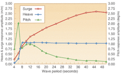
The offloading system comprises an FPSO, two oil offloading lines, and a CALM buoy. For incident wave periods greater than around 8 sec, the first order surge predominates. The surge response characteristics of the CALM buoy are crucial to the design of offloading lines. This is because the first order surge motion at the oil offloading buoy hang-off location is critical to its fatigue performance.
Offloading line fatigue
Offloading line design is largely driven by fatigue considerations resulting from first order surge motions of the CALM buoy. Both coupled and de-coupled analyses will reveal this; however, the coupled approach demonstrates the effect of the simplifications inherent in the latter approach.
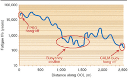
A frequency domain fatigue analysis of a 20-in. steel oil offloading line (OOL) was carried out using the frequency domain riser analysis program, Freecom-3D, and the fatigue postprocessor, Life-3D, also incorporating coupled CALM buoy motion characteristics and West Africa sea state data. The fatigue life prediction along the OOL clearly illustrates that there are two critical areas with respect to OOL fatigue life, at the CALM buoy hang-off point and in the mid-water buoyancy section.
Selection and distribution of buoyancy modules and the location of the hang-off point at the CALM buoy are critical to the surge-induced fatigue performance of the offloading line. This has resulted in the on-going investigation of de-coupled offloading systems, in an attempt to de-couple the motions of the CALM buoy from the attached offloading lines.
Conclusion
CALM buoy offloading systems are being widely considered for deepwater West African floating production systems. In deepwater, the apparent weight of the offloading and mooring lines is not negligible relative to the weight of the CALM buoy, hence their impact on the first order response characteristics of the CALM cannot be ignored. A coupled approach must be adopted for the analysis of these systems.
Analysis of a representative West African FPSO-OOL-CALM buoy offloading system has shown that the design of the offloading lines is largely driven by fatigue loading induced by first order surge motions of the CALM buoy. The critical areas for fatigue are at the CALM buoy hang-off and in the mid-water buoyant section of the offloading lines.
References
State-of-the-Art Report, "Tools for Hydrodynamic & Structural Analysis," Doc. No. TN-MCS-A-001, Rev. D, June 2002. EC Contract G3RT-CT-2000-05007 (FLOATTECH).
Technical Note for Flexcom-3D Version 5.5.2, MCS International, February 2002.


