Thermal flare gas flow meter solves measurement challenges on FPSO vessel
Innovative metering system deployed on Alvheim FPSO in the North Sea
Børge Olafsen, Aker BP ASA
Simon Obaro, Flow-Teknikk AS
Richard Koeken, FCI
The accurate measurement and disposal of flare gases aboard floating production storage and offloading (FPSO) vessels is essential to manage these potentially hazardous combustible, flammable and toxic gases. Accurate measurement of these waste gases allows them to be processed efficiently and effectively to protect people and equipment aboard the vessel. Measuring of flare gas is also most often a strict regulatory requirement, as it can form the basis for payment of environmental taxes, climate quotas, etc.
The dangers of improper hydrocarbon gas handling are well known and are regulated strictly by international safety organizations. The combustible and flammable properties of hydrocarbons make their handling a highly regulated process, requiring flow meter design certifications from multiple international approval agencies including FM, FMc, ATEX and IECEx to name a few.
Measuring flare gas is challenging for several reasons. These issues include mixed gas compositions, highly variable flow rates, large line sizes, lack of available pipe straight-run, limited access for installation or maintenance, and the effects of corrosive sea salt water and air. Only a few flow meter sensing technologies are robust enough to meet these many demanding requirements while providing accurate and consistent gas flow measurement.
The problem
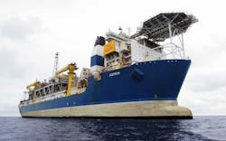
Aker BP ASA, one of the largest independent offshore oil companies in Europe, began to experience flare gas measurement accuracy and consistency issues aboard its Alvheim FPSO vessel. This FPSO vessel is located in the central part of the North Sea, close to the UK sector, and produces about 100,000 b/d of oil, including gas passing through its production pipelines and various metering stations (including those for flare gas).
The vessel’s engineers reported that the ultrasonic flow meters on the flare gas vent lines had stopped working at higher flow rates. They identified liquid condensation on the ultrasonic meter transducers and other challenging installation conditions as possible causes of the meter failures for which there was no immediate and/or permanent fix available to them.
The vessel’s engineers then researched alternative flow sensor technologies from several meter manufacturers for a new solution to measuring vent line flare gas. After contacting Fluid Components International (FCI), its applications team recommended the thermal dispersion ST100 Series Flare Gas Meter.
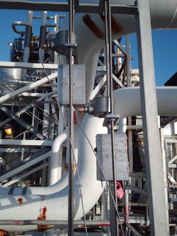
An innovative solution was chosen: The two existing thermowells used for dual temperature measurement as input to the ultrasonic flow meter were removed and standard 18-in. isolation ball valves were installed. By doing so during a process shutdown, it meant that the ST100 probes could be installed at any time at a later stage. The built-in temperature measurement of the ST100 thermal meter was then re-routed to the existing ultrasonic flow meter, thus keeping the original measurement intact.
The selected thermal flow meter configuration included an in-situ calibration verification system and stainless steel local and remote enclosures, which are designed for offshore flare gas systems. With no moving parts or orifices to plug or foul, thermal mass flow meters are virtually immune to clogging by dirty gas, require almost no maintenance for continuous operation, and offer a lower lifecycle cost.
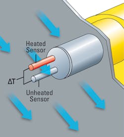
Thermal flow meters rely on the thermal dispersion principle of operation to measure gas. This technology places two thermowell protected platinum RTD temperature sensors in the process stream. One RTD is heated while the other senses the actual process temperature. The temperature difference between these sensors generates a voltage output, which is proportional to the media cooling effect and can be used to measure the gas mass flow rate without the need for additional pressure or temperature transmitters.
To comply with local regulations, which are intended to protect the environment through the monitoring of greenhouse gases (GHG), the reporting of (vent) flare gases should be done accurately over the entire flow range. The calibration of the chosen thermal meters was based on the actual gas composition as close as possible to the flare gas composition and the vessel engineers’ desired flow range, with calibration performed at FCI’s unique actual gas calibration laboratory.
The thermal meter selected can store up to five unique calibration curves to accommodate differing gas mixtures, multiple flare gas compositions, and it obtains up to 1000:1 turndown ratio. Measurement accuracy is 0.75% of reading + 0.50% of full scale with a maximum of 5% of reading over the entire 1000:1 turndown. The thermal flow sensing element measures flow from 0.07 to 305 Nm/s (0.25 to 1000 SFPS).
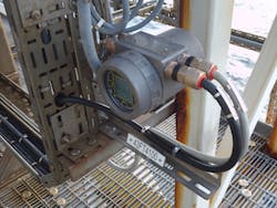
The selected thermal flow meter is agency approved for hazardous environments, including the entire instrument, the transmitter and the rugged, NEMA 4X/IP67 rated remote enclosure (Fig 3). Instrument approvals in addition to SIL-1 include ATEX, IECEx, FM and FMc.
When it comes to outputs, this meter offers all the most popular solutions: 4-20 mA analog, frequency/pulse, alarm relays or digital bus communications such as HART, Fieldbus, Profibus or Modbus. Also standard is an on-board data logger with an easily accessible, removable micro-SD memory card capable of storing 40 million readings.
Flow meter testing
The FPSO vessel’s engineers designed a test protocol to compare the thermal and the ultrasonic meter. Their objectives included:
• Find a dependable solution for accurate measurement at higher flare flow rates
• Investigate whether existing ultrasonic flare meters work as well as intended
• Be on the forefront of technology.
As mentioned, the thermal mass flow meter with its built-in temperature measurement was connected to the flow computer, and the temperature reading was shared with the existing ultrasonic flow meter for correct conversion from line to standard condition flow. The ultrasonic meter is located 1 meter upstream of the thermal meter.
The 18-in. [DN450] vent flare gas flowline on the FPSO vessel was monitored with a dual-averaging thermal dispersion sensor element configuration for better accuracy and to compensate for the larger line size and limited installation length. With the dual-averaging sensor design of the thermal flow element providing built-in temperature measurement, the vessel’s engineers were also able to eliminate the cost and installation complexity of adding two additional thermowells/temperature sensors. Two existing thermowells were basically replaced with two ST100 probes with built-in temperature measurement.
The thermal dual-averaging flow meter installed included the following specifications:
• Calibration flow range: Extended with more than 26 flow points and max 5% accuracy of reading accuracy over entire flow range
■ Normal operating: 60 – 850 NCMH [0,11 to 1,50 Nm/s]
■ Upset conditions: 850 – 172500 NCMH [1,50 to 304,66 Nm/s]
• Calibration media: Actual flare gas (offshore, upstream, stable gas composition):
■ Methane 93%
■ Ethane 4.58%
■ Carbon Dioxide 1.16%
■ Nitrogen 0.91%
■ Propane 0.27%
■ n-Hexane 0.06%.
Both of the new dual-averaging thermal flow sensor probes were installed in existing flanged process connections, previously used for thermowells and temperature elements, through full-bore ball valves in series with the existing ultrasonic meter for a one-year trial. The reason for having these probes in the upper half of pipe ID was the suspected stress/high torque that might occur on the probes with long entry during full flow/upset flaring situation because the pipe ID is 18 inches. This was slightly different than the suggested 15% and 85% of pipe ID installation depth.
Test results
The metering system’s July 2019 daily report for flare activity confirmed that the thermal meter correctly reported 54,000 Nm3/hr, while the ultrasonic meter (blue) incorrectly reported only 7394 Nm3/hr, due to the limitation of max flow capabilities of the ultrasonic meters. Based on the overall experience with the thermal meter, the FPSO vessel engineers concluded that for new flaring systems/production installations, the company would prepare piping for insertion type thermal mass flowmeters by adding flanges and valves for easy installation. Thermal meters were judged to be a cost effective and simple solution to measure flare gas across the entire flow range.
The July monthly summary report indicated a mismeasurement where the ultrasonic meter was not able to measure correctly; while the thermal meter was able to measure as expected. The export gas flow was redirected to the flare line due to a process upset. After the flow was redirected, almost instantly the thermal meter correctly measures the same flow rate in the flare gas line and follows the trend, while the ultrasonic meter is incorrectly measuring only 15% of the real flare gas flow. In these situations, it has been convenient to just use the thermal meter’s daily figures for daily flare gas reporting.
During a trip condition, the complete gas export flow is redirected to the flare where the new thermal meter immediately measures the same maximum flow as expected (equals gas export flow), while the ultrasonic meter is measuring only 20% of this flow. The result is a huge difference in totalized flow and demonstrates that a large amount of flare gas is not measured by the ultrasonic meter.
Moreover, the vessel’s engineers were aware that ultrasonic meter calibration checks had to be verified in the field by requesting the meter supplier to check the ultrasonic transducers in a “zero box.” This process typically took a total of three days (including time to get on-site) at a cost of approximately €10,000.00 for every verification.
In comparison, the installed thermal mass flow meter is able to perform a complete self-verification of calibration using a simple nitrogen connection/bottle. With this optional accessory to the basic meter, there is no requirement to shut down the line, pull the meter, install a spare and paying a lab fee to help meet air quality management regulations. •


