Torpedo piles show promise as cost-effective solution for deepwater mooring in GoM
Over 200 used offshore Brazil
Jean M.E. Audibert - Fugro-McClelland Marine GeosciencesMaurice N. Morvant, Jeong-Yun Won, Robert B. Gilbert - Department of Civil Engineering, University of Texas
Deploying conventional anchor systems for Mobile Offshore Drilling Units (MODUs) and for permanent facilities can be costly. However, decades-old technology, supported by reliable modeling algorithms, may provide a more cost-effective solution in the future for mooring deepwater facilities in the Gulf of Mexico.
During the last 10 years, Petrobras, the Brazilian oil and gas operator, has reported successful use of more than 200 torpedo piles, large cylindrical projectiles, as an economical method for anchoring deepwater facilities in the Campos basin, offshore Brazil.
Recently, several US operators have shown increased interest in torpedo piles for deepwater mooring, but lack of experience and an analytical database have made approval from the American Bureau of Shipping (ABS) and the Minerals Management Service (MMS) uncertain.
A series of torpedo pile experiments sponsored by Fugro-McClelland Marine Geosciences at The University of Texas at Austin, using large soil bed facilities, have yielded promising results, which will allow operators to predict torpedo pile potential embedment reliably, and, thus, anticipated axial capacity.
Current use
MODUs and permanent facilities are anchored to the seafloor using a variety of systems, including driven piles, suction caissons, suction-embedded plate anchors (SEPLAs), vertically loaded anchors (VLAs), and drag embedment anchors.
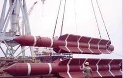
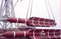
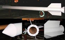
Torpedo piles for offshore use have come in two sizes: 30-in. diameter x 39-ft long, 54 kips; and 42-in. diameter x 39-ft long, 140 kips, both with fins and instrumentation.
Petrobras has deployed 30-in. diameter torpedo piles to anchor its FPSOP-50 in the Campos basin. The torpedo piles were taken to their anchor location and lowered to the required depth by winch. Once in position, the piles were allowed to free fall from 100-500 ft (30-150 m) above the mudline, reaching impact velocities ranging from 33-72 ft/sec (22-49 mph). The achieved penetrations varied depending upon the soil conditions, but reached twice the torpedo pile length in mostly clay or un-cemented calcareous sand profiles.
The technology has great potential in the deep soft clays of the GoM, but extensive modeling and reliable prediction of potential impact velocities and penetration depth for various soil conditions was needed before their use for permanent facilities could be sanctioned by ABS and the MMS.
Historical data, modeling
Torpedo-shaped projectiles were disposable soil testing devices as early as the late 1960s. These inexpensive, easily deployed penetrators could supplement geophysical travel-time profiles by estimating the shear strength of the seabed based on the penetration and deceleration of the free falling body.
Acoustic telemetry provided penetrator acceleration/deceleration data, from which the penetrator’s velocity and position could be determined. From these early studies, it was understood that the penetrator’s velocity at the time of impact with the soil surface would be a key element in predicting how deep the penetrator would sink below the soil surface.
Since 1977, more than 23 papers and articles have been written on torpedo piles and other seafloor penetrator experiments, covering the results of 53 laboratory tests on anchors ranging from a fraction of an inch (6 mm) up to 2 in. (50 mm) in diameter and 19 in. (480 mm) to 30 in. (755 mm) long.
Included were the results from 80 field tests both onshore and offshore on piles 3-in. (75 mm) in diameter by 69 in. (1.76 m) long, up to 30 in. (0.76 m) in diameter by 40 ft (12 m) long, with impact velocities ranging from 7.5-80 m/s (27-290 km/h).
During the 1980s, the Nuclear Energy Agency (NEA) evaluated the feasibility of high-level radioactive waste (HLW) disposal within deep ocean bed formations using large (up to 100 metric tons) torpedo-shaped projectiles (penetrators), allowed to free-fall 21⁄2-3 mi (4,000-5,000 m) through the water column, thus impacting the seafloor at terminal velocities of up to 300 km/h and typically burying themselves 100-130 ft (30-40 m) into the ocean floor.
Also in the early ’80s, the UK Building Research Establishment (BRE) carried out two sets of sea trials using models of the HLW penetrators, called Deep-Ocean Model Penetrators (DOMP), in conjunction with the NEA’s study.
The DOMP I tests were performed offshore West Africa in 1983. Four devices were deployed off the vesselRRS Discovery. With an air weight of 1.8 metric tons, a diameter of 1 ft (0.325 m) and a length of 10 ft (3.25 m), these penetrators reached a free fall terminal velocity of approximately 160 ft/s (180 km/hr) in 16,000 ft (5,000 m) of water and penetrated approximately 100 ft (30 m) into the soft calcareous ooze present. DOMP II tests were carried out offshore Puerto Rico.
Tests at UT-Austin
The model test program at the University of Texas at Austin covered various conditions such as load directions (axial and inclined load), drop heights, and projectile specifications (size and weight).
First, an embedment prediction model was developed and had to be calibrated. The researchers used Newton’s second law coupled with API 2002 offshore pile capacity equations to develop an analytical model to simulate the undrained vertical penetration of projectiles into the ocean floor.
Once the model was established, a series of comprehensive model torpedo experiments, using approximately 1:30 scale model test facilities and instrumentation systems, were conducted at UT.
These facilities and systems initially were developed and had been used over the last eight years to perform experiments on model suction caissons. The experimental set-up was modified to accommodate the torpedo pile research.
An aluminum frame provided overhead support for a pulley with a 1 mm diameter cable positioned above and attached to the torpedo pile model on one end and to a displacement sensor slide on the other.
Once the vertical distance between the mud line and the tip of the nose of the torpedo pile had been set to the desired drop height, a nylon cord was attached from an anchor point to the displacement sensor slide.
Deployment was triggered by cutting the nylon chord, allowing the torpedo pile to fall freely, impact the mudline, and embed itself into the normally consolidated kaolinite deposit.
The torpedo pile came to rest in the kaolinite bed only a second or so after deployment and was allowed to “set up” anywhere from hours to days. Once a specified set-up time had been reached, a load cell was mounted before the last stage or pull out to determine load capacity.
Torpedo pile testing
In the near future, the researchers plan a limited number of offshore field tests in the GoM using an 11.75 in. (0.3 m) diameter and 20 ft (6 m) long torpedo test pile, which has been fabricated and is ready to be deployed.
To minimize test costs, deployment will be conducted in shallow waters first, in conjunction with a geotechnical site investigation. The torpedo pile will be installed after anchoring the geotechnical boat (before starting to drill and to test the soil) and embedment/pull tests will be conducted to verify pull-out capacity after various soak times.


