Minimum facilities platform provides alternative for marginal field developments
Graham Nicholson
Yann Helle
2H Offshore
Recent interest in marginal shallow-water developments has led to a growing demand for cost efficient wellhead platforms which enable increased production capacity within existing field infrastructure. Wellhead platforms, or minimum facilities platforms (MFPs), typically house the surface wellheads, trees, and manifolds but do not include extensive process or separation facilities. As such, multi-phase production fluid may be exported from the MFP either to an adjacent production facility or into a larger field production network to be processed on existing assets.
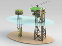
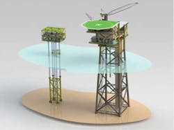
The Conductor Supported Minimum Offshore Structures (known as CoSMOS platforms) use the well conductors to support the topsides, thus eliminating the need for a separate supporting jacket structure. They offer benefits in terms of modular design, fast procurement, low fabrication cost, and ease of installation since they can be installed from a jackup or crane barge without the need for more expensive installation vessels.
The following focuses on the key design elements of conductor supported platforms and their advantages to achieving cost efficient platforms for marginal developments.
Platform design
MFPs typically are installed in shallow water for marginal field developments, satellite development, or infrastructure expansion. Many MFPs are developed from traditional platform designs and are supported on battered leg jackets; however these are costly to fabricate and install because of the size and weight of the jacket structure and associated piles. In recent years innovative designs instead use the strength of the well conductors to support the MFP topsides. This approach eliminates the need for a traditional jacket structure.
Conductor supported platforms rely solely on the strength of the well conductors to support the topsides but may also incorporate a subsea template or mid-water brace for additional stability. The conductor size is based on the structural design requirements, so a larger conductor may be required for the four supporting members than would otherwise be necessary simply to house the casings. To avoid the use of excessively large conductors, the platforms are best suited to mild or benign environments and in shallow to medium water depths. In deeper water the stability and fatigue performance of the conductor are reduced and additional support may be required.
The benefits of the CoSMOS type platform derive from the fact that the system is engineered to fit the requirements of a specific field and as such, each platform design is different. This is because each is designed to minimize the steel requirements, which reduces procurement and fabrication time. The platform is also designed primarily around the installation procedure that is considered to best meet the field requirements. The advantage is in designing a platform that can be shipped using conventional supply vessels and does not rely on a large crane barge for installation. This can have cost savings for the installation as it reduces the number of vessels required for the installation and their associated mobilization/demobilization cost.
The fundamental elements of the conductor supported platform are as follows:
Topsides. The topsides are designed to accommodate the wellheads, trees, piping manifolds, wellhead control panel, and any other required processing equipment. The overall weight and dimensions are largely defined by the project and the method of installation. For this type of platform, the piping system is integral to the platform and is not installed separately so as to save weight. The topsides also provides a structural connection to the conductors, thus defining the conductor end condition ("pinned" or "fixed"), which affects the conductor fatigue life.
A simple seated arrangement provides axial (compressive) and lateral load transfer, similar to a pinned connection; while a fully clamped design constrains the conductors in all degrees of freedom, similar to a fixed support. The clamped (fixed) connection is more complex and costly but usually provides improved fatigue response. For both scenarios, the effect of the constraint is limited by the stiffness of the topsides.
The topsides layout varies depending on whether the platform is manned or unmanned, and the project specific requirements including equipment, accessibility, and craneage.
Conductors. The conductors provide structural support to the topsides through axial compression and bending resistance, and support the well casings, wellhead, and surface tree. The total conductor length is defined by the water depth at the platform, the topsides elevation, and the foundation piling depth. The conductors are susceptible to extreme fatigue loads, the effects of which may be managed by controlling the number of conductors and their outside diameter, wall thickness, material, free span length, and connection type. Due to the dynamic loading on the conductors, fatigue enhanced connector designs are usually preferred for increased fatigue life of the conductors above the mudline. The typical diameter of the conductor used to support the platform is 30-in. or 36-in., with thicknesses ranging from 1 in. to a maximum of 2 in.
In addition to providing structural support for the topsides, the main function of the conductors is to house the wells. The minimum number of conductors is determined by the well count. A conductor can be configured to house a single well or multiple wells through the use of splitter wellheads. Additional conductors may be added to a platform to increase production capacity and/or improve structural performance of the system. Additional conductors may be either "free standing" (i.e. not structurally connected to the topsides) or "structural" (i.e. structurally connected to the topsides by a pinned or fixed type connection). Free standing conductors only provide additional production capacity and do not aid the platform's structural performance. Lateral loading generated by conductors needs to be considered in the design of the platform. Additional structural conductors provide increased support for the topsides and greater structural stiffness.
The selection between a pinned or clamped structural conductor depends on the overall performance of the system, and can be driven by environmental fatigue. Typically with a pinned type conductor, the platform seats on the conductor using a support shoulder. While this type of connection is cheaper and faster to install, there is a penalty in the fatigue life of the CoSMOS system that needs to be evaluated. Clamped conductors are used when fatigue life needs to be improved by increasing the stiffness of the overall structure.
As the free span of the conductor increases, so does the fatigue damage along its length. As for the top connection to the topsides, the connections of the conductor joints along the length are also fatigue sensitive. This makes it necessary to determine the best balance between cost and acceptable fatigue life.
Subsea template. The subsea template ensures correct space-out of the platform legs and provides a guide for any subsequently installed conductors. Additionally, depending on the requirements of the development, the template can be grouted or clamped to the conductors to provide structural support by increasing the system stiffness. In deepwater, the height of the template can be increased to reduce the free span length of the conductor. The template provides lateral support and stability for the conductor legs, and height can be varied to suit the conditions. For water depth less than 10 m (33 ft), the template requirement can be waived, and in shallow water (less than 20 m/66 ft), the template may be very short. However, in deeper water a much larger template may be required.
Typically, the height is driven by the fatigue performance of the conductors. This also depends on the total weight of the topsides. The heavier the topsides, the more bending stress is transferred to the legs during dynamic motion. In this scenario, a higher template may be required to reduce the deflection of the platform. Alternatively, the number of conductors rigidly connected to the topsides can be increased to enhance the stiffness of the platform, and thus reduce the deflection.
Design drivers
All conductor supported platforms consist of the same three fundamental elements, but each platform must be tailored to suit the following specific design requirements:
Water depth. Conductor supported platforms are suited for water depths of up to 50 m (164 ft). However, designs can be feasible for water depths to 70 m (230 ft) or beyond, depending on the specific application.
Environmental conditions. Benign environments such as in West Africa, Middle East, or Southeast Asia are better suited to ensure high fatigue life of the system.
Soil conditions. Conductor supported platforms can be used in a range of soil conditions, but weak soil may require additional piling depth to ensure adequate stability of the platform.
Well count. In cases where the platform is to be installed using a jackup mobile offshore drilling unit, then the combined installation clearance and drilling envelope restrictions typically limit the number of well slots to a maximum of nine.
Processing/equipment requirements. Conductor supported platforms best suit minimal facility applications. Optimal topsides dimensions typically are within 15 m x 10 m (49 ft x 33 ft), with a topsides weight up to 300 metric tons (330 tons). The platform equipment must be accommodated within this dimension and weight. Larger/heavier topsides can be designed; however, these may require additional structural support and alternate installation processes which may reduce the advantages of a conductor supported platform design.
Design life. A typical design life of 20 years can be achieved. Where lower fatigue life is required (e.g., a field of less than five years oil extraction), the design can be further simplified.
Installation. Conductor supported platforms are designed to give the operator as much flexibility as possible in terms of vessel requirements and scheduling when to install the platform and conductors. This can be done in advance by a crane barge to pile the conductors and to lift the topsides, or by the jackup prior to commencing drilling operations.
Frequency of human intervention. MFPs are typically unmanned platforms, with only short-term intervention for pigging, chemical tank refill, or general inspection or maintenance. Access is typically via boat although platform with helipads can also be considered. If longer-term manned intervention is required the platform access and safety requirements must be reviewed.
Tieback/interfacing. The requirement for fluid export or control lines such as umbilicals, flexible risers, and steel pipelines may necessitate the use of additional support frames and protection structures.
Platform behavior
The most important aspects of the structural response of a conductor supported platform are strength, wave fatigue life, conductor stability, and boat impact.
The greatest challenge in designing a conductor supported platform is to understand the dynamic response of the system under environmental loading. Due to the relatively low stiffness of the conductors (compared to a conventional jacket structure), the platform can exhibit significant deflections and high stresses resulting in impaired fatigue life.
Jackets are typically designed with a high structural stiffness, large footprint, and widely spaced piles. For CoSMOS type platforms, the conductors act as the piles but because of the much narrower footprint the stability of the structure is reduced. This leads to deflection of the platform and topsides, and hence dynamic loading of the conductors.
Wave induced fatigue is usually the most critical design driver for a conductor supported platform. The conductor fatigue life is dependent on the free span distance between the seabed (or subsea template) and the connection to the topsides. The greater the span, the less stable the system and the more bending moment is transferred to the conductor under wave loading. For water depths around 40-50 m (131-164 ft), the subsea template provides the effect of artificially raising the seabed to reduce the free span in the conductor leg, thus improving the stability and fatigue life of the system. By increasing the footprint on the seabed or constraining the conductors at the template and the topsides, overall stiffness of the structure can increase and the height requirement of the template can decrease. The use of fatigue-optimized conductor connectors also improves the fatigue response of the conductors.
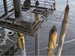
Increasing platform stiffness may improve the platform fatigue response, but may reduce boat impact resistance. For a conductor supported platform, the conductors are not protected by a jacket and therefore are vulnerable to direct impact. As the conductor may carry internal well casings, the platform structure must be sufficiently compliant to absorb the impact energy to avoid excessive damage.
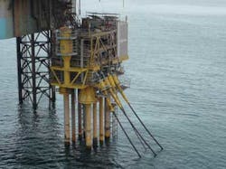
The trade-off between platform stiffness (fatigue resistance) and system compliance (boat impact resistance) drives the selection of the conductors and template dimensions. A longer free span of the conductor will provide more deflection, and hence more impact energy can be absorbed without damage. However, the greater deflection leads to more fatigue damage under long-term wave loading. If large energy absorption is required, additional boat impact bracings can be added close to the mid-water level to provide additional energy absorption.
Installation considerations
One major advantage of a conductor supported platform is that it can be designed for installation by a jackup drilling rig. The main benefit is in using the same vessel for piling the conductors, drilling the wells, and installing the platform. This can simplify installation and avoid the additional costs, complexity, and risk of using multiple vessels.
When the topsides weigh more than 250 metric tons (275 tons), it can be designed to be lifted in two separate parts so that the crane on any installation vessel is suitable for the lift. Typically, the weight of the topsides prior to offshore fitting is about 150 metric tons (165 tons) and the subsea template is about 100 metric tons (110 tons), making the use of a relatively small crane possible.
When compared with the installation of a typical jacket structure, the installation of a conductor supported platform is simpler and faster. There is no requirement for pre-installation of piles before installing the platform (as the well conductors also act as the template piles), and due to the much smaller sizes of the structures, the transportation and lift requirements are greatly reduced.
Conclusions
The CoSMOS system may offer cost and schedule savings for applications where traditional jacket platforms are uneconomical or where specific design requirements or constraints need to be met. Cost savings can come through the use of the jackup for installation, or through the use of other lower specification vessels for transportation and installation when compared with those required for a jacket. Other cost savings can come from reduced procurement, fabrication, and engineering requirements. Schedule optimization is achieved through use of pre-engineered modular designs for key components. This method can also significantly reduce the front-end engineering and design and detailed design duration.
The advantages of the CoSMOS platform concepts are maximized in applications where minimal platform facilities are required in regions of water depth in relatively benign environments up to 50 m. The CoSMOS platform offers a proven marginal field development solution as an alternative to a conventional jacket structure. The system is defined as an engineered solution that can yield cost saving for the operator in terms of engineering, procurement, installation, and schedule.
Acknowledgment
p>Based on a paper presented at Offshore West Africa Conference & Exhibition held March 19-21, 2013, in Accra, Ghana.


