The value of saving raw log data
Rich Hardman,6FF40
Otto Fanini, Jack McGinnis, Riley's Electric Log
In a deviated well, it is extremely important to save the measured resistivity raw data. Logging companies typically process the raw resistivity data with software that assumes the well is vertical. Under this assumption, wrong resistivities are obtained in deviated wells resulting in formation evaluation errors. If archived, this shortcoming can be overcome by reprocessing the raw data with recently developed techniques.
Most oil-bearing formations were deposited in an ocean environment. As a consequence, the pore spaces of the reservoir rocks contain either salt water or hydrocarbons. The salt water makes the rocks conductive to electricity, and the hydrocarbon makes the rocks resistive. The initial-oil-in-place (IOIP) representing the volume of oil (Vo) in a reservoir is calculated by Vo = reservoir area x thickness x porosity x (1-Sw) where Sw is the water saturation.
The water saturation is calculated in a clean sand by Archie's equation Sw = SQRT (Rw/(Ø2 x Rt)), where Rw is the water resistivity, Ø is the porosity, and Rt is the true resistivity. The Rt and porosity are obtained from the logs. If Rt increases, Sw decreases and Vo increases. For a given porosity, if the resistivity is higher, the volume of oil is higher. There have been reservoirs that have produced more than the IOIP because the Rt was wrong. This can be very embarrassing.
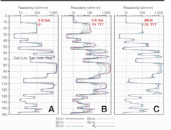
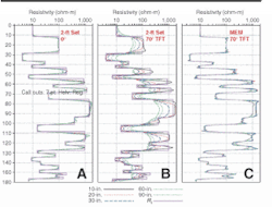
Array Induction Tools have eight spacings varying from 6 in. to 72 in. As a consequence, these tools do an excellent job of measuring the formation's resistivity. However, the raw data is processed at the well site assuming the tool is at right angles to the layers. When this assumption is met, the processing can resolve and even evaluate the three 2-ft beds located at the bottom of the Oklahoma formation. The older 6FF40 induction tool with 40-in. spacing could not resolve these thin beds.
The terms deviated and vertical hole are sometimes used loosely. What is important is the apparent dip angle, which is the angle between the hole and the bed's normal or perpendicular.
At 70° apparent dip, the tool still acquires good raw data. However, the processing, which assumes right angles or 0° apparent dip, yields incorrect results because of the failure to account for dipping beds. For example, the almost 20-ft true vertical distance (TVD) bed between 80 ft and 90 ft reads only 400 ohm-m, instead of the actual reading of 1,600 ohm-m. In this case, the water saturation, Sw, would be off by a factor of two [SQRT (1,600/400)]. This 20-ft TVD bed has an apparent thickness of 40 ft on the field log. Most geologists or petrophysicists would think that a 40-ft bed would read Rt, but it is off by a factor of four (1,600/400). The errors from incorrect processing are even worse for thinner beds.
Recently Schlumberger developed Merlin (MEM) processing, which includes the Hardman fast computation of the derivatives. This algorithm performs fast processing of the raw induction data to produce excellent results. At 70° this processing is capable of resolving and evaluating 2-ft beds. Since the inversion (going from raw data to Rt) is highly nonlinear (doubling the Rt of a bed does not double the log response), an iterative approach is the only practical inversion solution. MEM processing requires six to eight iterations.
This improved processing is possible only if the raw data is available. Induction instruments measure a voltage. In an infinitely thick bed there is a correspondence between this measured voltage and conductivity (1/Rt). For Schlumberger's AIT tools, this conductivity is the fully calibrated (FC) data. This data is then borehole and tool geometry corrected to generate the borehole corrected (BC) data. The tool geometry correction accounts for proprietary tool details. This is why the BC data should be saved as well as the FC data. The BC data is then processed to generate the 10-, 20-, 30-, 60-, and 90-in. resistivity log curves.
Most users think this is the measured raw data; it is not. Both the FC and the BC data in DLIS format must be saved and stored off-depth:
- For the Platform Express (AIT-H), the data files are AHIFC and AHIBC
- For the SlimAccess (SAIT), they are ASIFC and ASIBC
- For the Array Induction Tools (AIT-B/C/D), Xtreme HTHP (HIT-A), and SlimXtreme HTHP (QAIT), they are AIFC and AIBC.
This article points out issues with the processing and archiving of induction tool raw data; however, the raw data for all other tools, such as Sonic and Nuclear, also should be saved. Several data archiving companies have the infrastructure to save the raw data, which can be important in finding bypassed oil. If thinly bedded formations are drilled at an angle, the electric currents in the formation are radically changed, and there is a better chance of detecting them. The 6-in. data by itself might detect thinly bedded turbidite formations. When thinly bedded formations are suspected, the raw data can be put on depth and displayed at the well site. This is the last chance to acquire additional information, such as an image log or sidewall cores, while the well is open prior to casing or abandoning the hole.
In a deviated hole, the IOIP can be significantly underestimated despite the acquisition of very good raw data. It is crucial to reprocess the raw data using updated technology. Since many users of log data think that the 10-, 20-, 30-, 60-, and 90-in. resistivity log curves are the raw data, the actual raw data (FC and BC) is not being saved. Some of this invaluable raw data is being lost forever, along with the opportunity to accurately evaluate the reservoir's IOIP. This evaluation is important for proper field development, facilities, and pipeline design. An economic benefit of a better IOIP is the reservoir's more precise monetary value.
References
Barber, T.D., Broussard, T., Minerbo, G.N., Sijercic, Z., Murgatroyd, D. 1999. Interpretation of multiarray induction logs in invaded formations at high relative dip angles. The Log Analyst, v. 40, no. 3, May-June, 202-217.
Hardman, R.H., and Shen, L.C. 1986. Theory of induction sonde in dipping beds. Geophysics, v. 51, No. 3, 800-09.
Hardman, R.H., and Shen, L.C. 1987. Charts for correcting effects of formation dip and hole deviation on induction logs. The Log Analyst, July-August, 349-56.

