Spar technology meets Atlantic Canada's deepwater challenges
Concrete design offers opportunity for local content
John Murray
Technip Offshore Inc.
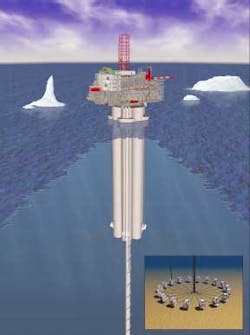
Deepwater spar technology is ideally suited to develop one of the most difficult regions in the world – Atlantic Canada's Orphan basin. A new disconnectable design allows the spar to move off station in the case of iceberg threat. The spar also offers about 1 MMbbl of storage and the ability to drill, complete, and perform well intervention and production from the same platform.
Reservoirs lying beneath the frigid waters of the Orphan basin at depths to 3,000 m hold resources in the order of 2.1 Bbbl of oil, 10 tcf of natural gas, and 450 MMbbl of natural gas liquids. The challenge is contending with the harsh environment to get the resources out of the ground.
Canada's east coast presents one of the most hostile offshore environments in the world. Besides having design wave, wind, and current conditions similar to the Gulf of Mexico, there is the additional challenge of ice.
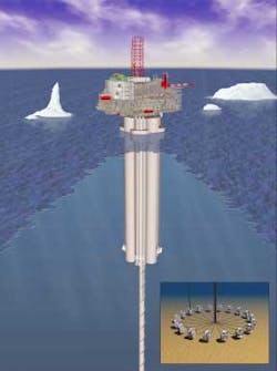
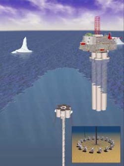
The spar design can withstand impact from small bergy bits, and sea ice can be managed through design features of the spar system. It is highly unlikely, however, that any floating structure could withstand the impact from a large iceberg. Therefore, the spar's mooring and riser systems are designed to disconnect. When an iceberg threat arises, wells can be shut in at the sea floor, and the flowlines can be flushed and disconnected at the spar keel.
null
Another consideration in Atlantic Canada is the lack of export infrastructure, which suggests that shuttle tankers will transport the oil from local storage. The spar's ability to store approximately 1 MMbbl of production becomes a critical capability.
Considering the expected size of the reservoirs, at least five systems of varying capability are envisioned for development over the next 10-20 years. Employing local engineering and construction resources, the new spar could provide the impetus to start and sustain an industry in that region.
Design and construction
The spar hull comprises six or eight storage cells arranged in a circular pattern, with each cell compartmentalized into a buoyancy chamber at the top and a reservoir in the lower section to store oil-on-water. As oil is taken on, water is displaced through a port at the bottom of the cell. The mixing layer at the oil-water interface is small because of the small sectional area in the cells. A similar arrangement has been used successfully for a number of years on the Condeep platforms in Norway, maintaining contaminant levels well below stringent local requirements.
The spar's hull can be constructed of steel or concrete. Each material has advantages. A steel hull offers the flexibility of being constructed in a wide range of facilities worldwide and can be transported to the mating site, up-righted, and topsides installed. The main advantages of steel are a smaller hull and fewer moorings. However, additional costs for hull transportation and more steps in the assembly process have to be taken into account.
null
Concrete, on the other hand, has better insulation properties in cold water and would be more attractive to local industry because most delivery scenarios favor construction near the deployment site – in this case, Newfoundland.
A construction method similar to that used on the Hibernia GBS could be used. A base section could be constructed on land and floated to the deeper water location nearby. The concrete hull would then be slip-formed to the required draft. The construction facility at Bull Arm in Newfoundland, originally commissioned to construct the Hibernia GBS, could perform this work.
In this scenario, the topsides are assembled on a barge, the hull is ballasted down to the appropriate draft, and the topsides are floated over. The spar is then deballasted to its tow draft and towed vertically to the installation site.
The buoyancy chamber at the keel is sized to support the mooring and riser systems when disconnected from the main hull. There is sufficient buoyancy in the chamber to support moorings and risers in the water column after a disconnection and to hold them in position until the section of the spar that has floated away is returned and reconnected.
The fairleaders and risers are supported in the water column away from the ice about 700 ft below the surface. Because of the water depth in which the spar is deployed, the influence of waves on the buoyancy chamber is small.
Reconnecting the system is relatively straightforward. The spar is positioned above the support of the section buoying the risers and moorings. A connection made through the center well reconnects the bottom section. An ROV could perform this procedure. During the disconnect procedure, support vessels control the hull. The moorings are run down the sides of the spar and arrested at the fairleaders, which are run on messenger lines that remain lowered to accommodate re-connection.
Mooring and riser systems
The mooring system is made up of a chain-steel-chain or chain-polyester-chain configuration. Preset moorings secure the hull at the installation site. A shroud, which is an integral part of the hull, protects the mooring lines from ice at the waterline.
Fairleaders are attached to the spar at the buoyancy chamber. Moorings can be attached at this low level because of the large GM (metacentric heights that are a measure of the initial stability of the system). The connection between the buoyancy chamber and the spar is a design consideration because it transfers mooring restraining forces to the main part of the hull from the buoyancy section.
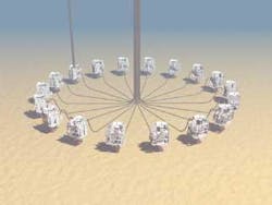
The riser system is made up of bottom-tensioned risers connected at the top directly to the deck. The upper section of risers passes through the centerwell and consists of a bundled array of single casing tubulars passing through the interior of the hull, where they are protected from the environment. Riser and well control lines at the keel connect by means of an interface template at the top of the lower buoyancy section. At the bottom, the riser bundle surrounds a pile driven into the seafloor, allowing the bundle to move vertically in response to vessel motions. Weights can be added to the bottom section to tension the risers as required.
A flexible jumper connects the bottom of the riser and the wellhead. Depending on the currents in the region, the riser bundle can be straked to suppress vortex-induced motion on the risers. Each riser can be shut off at the wellhead and flushed between the wellhead and the spar to prepare for disconnect. These flexibles have excellent resistance to fatigue damage.
null
The spar can be equipped with a riser used for drilling, completion, and subsequent workover. This riser enters the subsea wellheads vertically above the well. One of the design constraints of this approach is that the pattern must be tight enough to access all wells by positioning the spar directly above the well using the mooring system. The maximum offset is generally a function of water depth, in the order of 7-10% of the depth.
Basic economics illustrate the advantage of drilling and performing well completion and workover from the same platform. The spar design is well suited to provide these capabilities, and with the high potential for local content in the construction and delivery of the systems, it is an attractive solution for deepwater Atlantic Canada. ;
Author
John Murray, PhD, PE, is a principal engineer with Technip's Floater Product Line in Houston, where he is involved in developing new deepwater systems. Murray has held positions as lead engineer and engineering manager for deepwater systems in the Gulf of Mexico. About 14 of his 25 years in offshore engineering have been spent in R&D. For more information, contact [email protected].


