Deepwater well re-entry model can save time, money
Marcio Yamamoto, Celso K. Morooka • State University of Campinas, Brazil
Seiya Ueno • Yokohama National University, Japan
The dynamics of a semisubmersible platform coupled with a free-hanging vertical rigid riser during the re-entry operation in ultra deepwater is complicated by the effects of platform motions on the installation procedure. The placement and installation is time consuming and requires accuracy to position the riser on the wellhead. This study examines the influence of platform motions on the re-entry operation in more than 1,500 m (4,921 ft) water depth. It also examines the motions on the drilling riser and BOP, which could lead to drilling more than one well without raising the BOP to the surface. A numerical simulation in time domain was conducted using a non-linear model for the platform dynamics. The dynamics of a free hanging drilling riser and a dynamic positioning system of the semisubmersible platform were included in the numerical model.
One purpose of this work was to investigate two different possibilities for a DPS control system, the floating platform with and without considering BOP and riser dynamic behavior. A feedback control system for the BOP position was proposed, and an additional feedback loop, external to the conventional DPS control system, was included in order to automatically control the BOP position during its approximation to a wellhead.
The proposed control approach reduces the overshot of the BOP displacement in a re-entry operation. In the presence of current, the proposed control shows good performance in bringing the BOP back to the original reference position over a wellhead.
The results indicate it may be possible to further improve the DPS control system in a floating platform to reduce time and costs involved in deepwater offshore operations. In addition, the high frequency loads caused by the vortex shedding (VIV) did not cause instability on the feedback control of the DPS for the cases simulated in both surge and sway directions
Re-entry operation
Re-entry entails positioning the BOP above the wellhead, approaching, and installing the BOP on the wellhead. During this operation, the BOP is lowered attached to the drilling riser. In this scenario, two coupled dynamic systems are identified. The first is the platform itself, including the DPS feedback control loop. The second is the BOP system including riser dynamics.
The platform position is controlled by the DP system. The DP feedback control considers space/state control feedback. Furthermore, the BOP position depends on riser dynamic behavior, the platform position, and the environmental loads (current and waves).
Nowadays, the installation of the hanged BOP onto a wellhead is carried out with the help of an ROV. The ROV camera shows the BOP position in relation to the wellhead, and the DP operator changes the platform position to reduce the distance between the BOP and the wellhead. This usually is time consuming because the BOP position control is manual.
An additional feedback loop is proposed for the coupled system to control BOP movement. The main purpose of this external loop is to control automatically the BOP position when it hangs by the drilling riser, to reduce re-entry time.
The standard semisubmersible platform of the International Towing Tank Conference (ITTC) was used for the numerical simulations. This semisubmersible has two pontoons, each 115 m (377 ft) long, 15 m (49 ft) wide, and 8 m (26 ft) high. The platform has eight vertical columns, with diameters of 10 m (33 ft) for the four external corner columns, and 8 m (26 ft) for the four central columns.
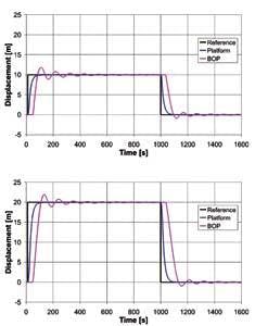
(bottom)Rectangle input with DPS (20 m).
The riser properties and main dimensions used in the simulations are shown in the accompanying chart. The BOP in the simulations weighs 300 tons (272 metric tons) with its mass assumed to be concentrated in the lower most element of the riser. Simulations were carried out in time domain, and the results were obtained for the coupled floating platform and riser dynamics when the proposed system was used. Furthermore, an additional external feedback loop was taken into account to control the BOP position. An integral term also was added to the external feedback loop to reduce observed stationary error, particularly evident when the current is high.
The time series of simulated results for the floating platform and the BOP displacements in the sway direction show the rectangle input control function of 10 m (33 ft) and 20 m (66 ft), respectively. In both cases, single DP that controls only the platform position is taken into account. The results indicate that the platform follows the rectangle shape position input towing the BOP by the drilling riser. When the platform reaches the input reference, it stops, but the BOP continues moving due to inertia. The result is an overshot of almost 2 m (6.5 ft) and then oscillation around the position.
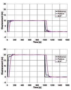
A second test was run using the same conditions plus an additional external feedback loop to control the BOP position. Before the platform reaches the target, its speed reduces or moves back to reduce the BOP displacement. No overshot was the result.
(bottom)Rectangle input with external feedback loop (20 m).
The platform and BOP displacement in the surge direction for the same conditions show the oscillations of the BOP position around 200 s and 1,200 s are caused by the VIV when the platform tows the riser and the BOP. The platform oscillation due the VIV can be ignored; these oscillatory loads did not cause instability on the feedback control of the DPS in the surge and sway directions.
Calculating the platform and the BOP displacements in sway in the presence of current with a triangular profile in relation to the water depth shows the BOP position shifted away from the reference due to current pushing the riser. The sea surface current speed is 0.6 m/s (2 ft/s) and zero at the sea bottom. In both cases, the input reference for the feedback control is the position zero. The same calculation with the additional external feedback loop to control BOP position changes the floating platform’s position in order to maintain the BOP in its original position in time.
A uniform current profile was considered in the simulations. A constant current speed of 0.6 m/s (2 ft/s) was factored in the sway direction. This case with only conventional DPS control showed good station keeping performance over a reference position. The BOP and riser were pushed away from that reference by the current loads. With the additional external feedback control, the BOP was pushed back to the original reference position, as in the previous results.
Simulations using an extreme uniform current profile showed stable oscillation of the BOP position. In this extreme sea condition, actual re-entry operation should be suspended until sea conditions improve. Oscillation in the results from the BOP control system is due to the extreme inclination of the riser in this case. System gains were tuned to control risers in the vertical or near vertical position. This discrepancy caused overshot and oscillations. The inclination of the riser is caused by current loads.
The oscillating loads caused by VIV on the platform are very small compared to the platform inertia. Therefore, its influence on platform oscillation can be ignored. The BOP vibration caused by VIV has average amplitude smaller than 0.4 m (1.3 ft), but with peaks of up to 1 m (3.3 ft).
Regular waves with a height of 3 m (9.8 ft) and a period of 10 seconds were added in the sway direction. The results indicate that the wave pushes the platform away from the reference position at 0 m, and then the DPS control activates the thrusters to bring the platform back to the initial reference position. The wave effect is stronger nearby the sea surface. It means that the wave acts mainly on the floating platform, and, the BOP displacement and oscillation resulted from the platform displacements enhanced by the wave.
Acknowledgements
The authors acknowledge the financial support of the Brazilian Petroleum Agency (PRH15- ANP/MCT), Petrobras, CNPq, and FINEP/CTPetro, and also the Japan International Cooperation Agency.
This article is based upon a paper presented by the authors at the 26th International Conference on Offshore Mechanics and Arctic Engineering.


