SEISMIC TECHNOLOGY: Matching outcrops to seismic can model deepwater reservoir deliverability
Deepwater clastic sedimentation is subsurface geology's 'dirty little secret.' Reservoir engineers deal with the consequences of the secret all of the time. The secret is this: Any depiction of subsurface stratigraphy using seismic and/or wireline logs is gross simplification.
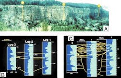
Roger Slatt (Professor at University of Oklahoma), and others (1994) provide an excellent illustration of the secret. They show a typical outcrop of deepwater channels and three outcrop-logs spaced at very close intervals approximately 500-600 ft apart (see accompanying figure). A perfectly reasonable correlation can be made using these logs and many geoscientists would choose such a correlation. However, the true correlation between these logs, based on detailed study of the outcrop is very different and complex. No geoscientist would be able to discern this level of complexity with only the three logs shown in the example.
Furthermore, 3D seismic data does not resolve the issue. The complex arrangement of sand and shale interbeds, which could have a huge effect on reservoir deliverability, occurs at a sub-seismic scale. 3D seismic data may show the effect of these sub-seismic variations by subtle changes in amplitude, but developing an understanding of what those subtle changes mean is not an easy task.
Ten years ago the no one would have cared. The industry drilled first and asked questions later. But most of the offshore wells being drilled then were on the shelf and had dry hole costs of less than US$5 million. Now, we are drilling wells in very deep water and dry hole costs are commonly more than $30 million. Developing a deepwater field may cost more than $300 million.
We must know if a field is going to be economic before we spend a lot of money drilling development wells. The better we understand the details of reservoir geometry at a sub-seismic scale, the better job we are going to do of determining whether a discovery has sufficient reserves to justify development. Then, we can develop that field in the most efficient way with the fewest wells.
This is especially true for fields in which reservoirs are characterized by multiple channel-fills.
Gulf of Mexico case
For many years, Green Canyon 184 (Joliet) has provided a cautionary tale, regarding the risks of prospecting for channel-fill reservoirs in deepwater. Joliet produces from multiple small channel fills that are pressure separated from one another. Each well drilled in the field has shown high initial flows. However, the flow rates decline rapidly as the individual channel fills are depleted. New wells penetrate new channels-fills and the story is repeated.
In contrast, Green Canyon 205 has a much happier story. Production comes from two main reservoirs, the N1 and N3 sands. Rafalowski, and others (1994) from Chevron, note that both sands show different types of channel-fill geometry. Sand connectivity in the N1 sand is fair to good and is excellent in the N3 sand in contrast to Joliet. The N1 sand is interpreted as a series of individual channel-fill sands separated from one another by levee or interchannel deposits.
Depositional lobes are also observed in this interval and some connectivity between channels occurs through the lobes and interchannel/levee facies. In fact, the interchannel/levee facies is an important pay interval in its own right. However, some channels are pressure separated from one another. The N3 sand is comprised of amalgamated, sand-rich channel-fills. This amalgamation results in excellent continuity throughout the reservoir interval. Younger channels that cut into older sand-filled channels are also sand-filled. Therefore, although the N3 is comprised of multiple channel-fills, it acts as a single, uniform sand.
A wide variety of types of channel fills are present in deep-water reservoirs of the world. Some, like the N3 sand in Green Canyon 205, show excellent connectivity. Others, like Green Canyon 184 (Joliet), show relatively poor connectivity. We see the same types of variation in outcrops.
This variability raises a key question: How can we assess the effect of variations in reservoir connectivity in deepwater channel-fill reservoirs, either pre-drill or pre-development?
Assessing variations
In many cases, we have some of the information we need. We commonly have very good seismic data and, in a pre-development situation, we have a few wells with excellent well-log suites. We may have FMI/FMS log and pressure data for these wells. However, the wells give us only limited information about the area beyond the wellbore. Although, sub-seismic changes in reservoir geometry may affect attributes of the seismic signal, individual channels and intervening shale intervals are commonly difficult to detect.
Sullivan, et al. (2000) of Exxon-Mobil came up with an innovative way of addressing this problem. They went to large surface exposures of deepwater channel systems where channel connectivity can be very accurately determined. At these locations, they asked the question: What do these surface exposures look like on seismic data?
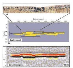
One of the units Sullivan et al studied was the Skoorsteenburg Formation that crops out in South Africa. This formation has been widely studied as an analog to deepwater reservoirs in the Gulf of Mexico. Sullivan and his co-workers carefully examined channel geometries in outcrops of proximal and medial fan facies. Then, they made forward seismic models of the outcrops.
A forward model is made by inputting specific rock properties and geometries into a program that then generates a pseudo-seismic section. Since they were developing these models as analogs for Gulf of Mexico deposition, they used subsurface rock properties from the Gulf of Mexico. Sandstone geometry and net-to-gross ratios came directly from the outcrop.
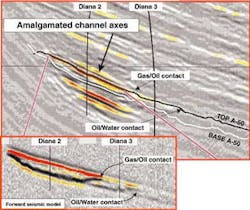
Forward models of the proximal fan facies were then compared to the 3D seismic data in the Diana Field. The forward model seismic sections looked remarkably similar to the actual seismic data over a part of the Diana Field characterized by proximal fan facies.
This indicated that channel geometries in this portion of the Diana are similar to those observed in the Skoor- steenburg outcrop. Sullivan et al also used forward models made from medial fan outcrops in Ireland and again observed a close comparison between the modeled seismic data and seismic over a part of Diana Field.
The close correlation between forward seismic models from the outcrops and actual seismic data from various parts of Diana Field suggest that data on channel connectivity collected from the outcrops could be directly applied to the subsurface.
The next step was to integrate a detailed study of the well log and core data into the forward model. Wireline logs were used to determine petrophysical properties of different sedimentary facies, which are then incorporated into the model. In addition, they adjusted the channel depths based on direct observation from the well-logs and the widths based on width/depth ratios derived from analysis of the outcrops. Finally, they incorporated fluid data based on observed gas/oil and oil/water contracts in the field. The final result was a forward model that was an even better match to seismic data from Diana field.
Reservoir modeling
After the construction of a descriptive geologic model, it is common practice for reservoir engineers to "upscale" or simplify geologic variables when creating a dynamic reservoir simulation model. These dynamic models are commonly quite complex and can tax the capacities of even the fastest computers. In addition, most projects require multiple simulations to best predict reservoir behavior and to properly match the simulation results to field history.
Consequently, simplification, or upscaling of the static model is done to speed computation time. However, there are times when upscaling can smooth the data to the point where any results from a simulation will be misleading. Because of the risk of smoothing, Exxon-Mobil actually elected to downscale and to build a more complex dynamic reservoir model in order to simulate the oil rim in Diana Field. This model contains reservoir quality data about channel geometry and connectivity collected from the proximal and medial fan outcrops. The ability to construct such a detailed model may result in a better development plan than would have otherwise been possible.
Slatt et al (2000) observed that outcrops, when sufficiently large, provide a means of capturing the appropriate level of reservoir heterogeneity for placement into a dynamic model for simulation. However, the question remains - Which outcrop?
Outcrops of the proximal fan portion of the Skoorsteenburg Formation fit a part of Diana Field quite accurately. However, a high degree of variability is present in deepwater facies, particularly in channel-fill environments. Part of the answer is in history matching. Comparing the results from the simulation to actual production history can test the effectiveness of using a specific outcrop as a guide to reservoir morphology.
History matching is difficult in fields that lack substantive production histories. In fields like this, the key is to use the same tools to look at both surface and subsurface intervals. Not only can forward seismic models of the outcrops be constructed, but simple reservoir simulations can be made from the outcrops themselves (Slatt; 2000). Once a good match is found between a specific subsurface example and its outcrop equivalent, and the match is confirmed by examination of all core, borehole imaging, and wireline data, we will have the information to make development decisions with an increased degree of accuracy. - Reservoir facies model of Diana Field showing changes from proximal highly amalgamated channel-fills (purple and blue colors) to medial distal channel-fill, which are separated from one another by thick mudstones (red colors). CA = channel axis, COA = channel off axis, CM = channel margin (from Sullivan and others, 2000 and reproduced with permission from the GCSSEPM Foundation).
Comparison of outcrop and subsurface intervals will always be an inexact science. The accuracy to which it can be done will depend largely on the ability of the geoscientists making the comparison. There has never been a "black box" answer in subsurface analysis despite many attempts to construct one.
There will always be risk and uncertainty in any decision to explore for, or develop hydrocarbon reservoirs. The better job we do of eliminating subsurface geology's 'dirty little secret,' the better job we will be able to do of predicting reservoir performance.
References
Reference list is available from the author - Jory Pacht in Houston, Texas (Tel: 713-532-5588 or Email: [email protected]).
