New insulation coating helps maintain product flow
Phil Collier
Tata Steel
For over four decades, oil and gas has been extracted from the United Kingdom continental shelf (UKCS) to provide energy. Oil and gas, which was once readily available not far from the coastline, now requires exploration much further from shore, at far greater depths, and at much lower temperatures. As a result, companies operating in the oil and gas sector have had to develop new technologies to fully develop mature assets which previously were too expensive to extract.
To accommodate production from these depths, operators need a sophisticated and resilient pipeline system, one that can safely transport products above temperatures at which solids could fall from suspension and block the pipe. One way to help operators maintain those temperatures is an effective insulation system.
Tata Steel has been at the forefront of steel technology for many years, and recently completed its first insulation coating pipeline project. The successful conclusion of this project came several years after development and investment in its joint venture coating facility, BSR Pipeline Services, located at the company’s pipe mill site in Hartlepool, England.
Project details
Awarded by Subsea 7 in July 2009, Tata Steel’s scope of work was to supply the coating of the pipe for the Total E&P Netherlands BV’s K5CU project. The work was for approximately 15 km (about 6 mi) of a 10-in. (25-cm) natural gas pipeline and the same quantity for a 3-in. (8-cm) di-ethylene glycol line. The majority of the pipeline was coated with a standard three-layer polypropylene coating, but 530 m (1,738 ft) needed an insulation coating with a U value of <6 W/m²K in the unburied state. The insulation coating was a four-layer polypropylene (PP) foam-based system, with a minimum thickness of 37.1 mm (1.46 in.) to achieve the required U value.
BSR four-layer system
The first layer of fusion-bonded epoxy (FBE) coating goes directly onto the pipe and provides the main anti-corrosion coating. The thickness of this layer is 250 – 400 µm.
The second layer represents a layer of strong polypropylene-based adhesive sprayed on top of the FBE coating to secure the polypropylene foam. The thickness of this layer is 250 – 400 µm.
The third layer is polypropylene foam, which provides the majority of the insulation properties, reducing heat transfer through the pipe wall and maintaining product temperature. The thickness of this layer depends on the required U value of the insulation coating system. For the K5CU project, a minimum thickness of 33.5 mm (1.31 in.) was required.
Overview of the four-later coating application process.
The fourth layer is a solid polypropylene topcoat. This outer tough layer protects the foam from damage during handling, pipe lay, and whilst in operation on the seabed. The thickness of this layer is usually a minimum of 3 mm (0.11 in.), which is standard practice for a three-layer system.
Coating application
BSR was established in 1988, as a joint venture between Tata Steel, which at the time was operating as British Steel, and Ramco Oil Services in Aberdeen. The plant was upgraded in 1998 to coat three-layer PP and polyethylene (PE) on pipes with an outside diameter (OD) up to 24-in., and then further upgraded in 2000 to coat pipes up to 48-in. OD. The company has an extensive track record for both onshore and offshore applications worldwide and has many experienced personnel. However, applying a four-layer system is a step change in complexity, consistency and quality. Some of the issues that need particularly close monitoring included:
- Coating thickness
- Line speed
- Quenching
- Foaming of insulation layer
- Extrusion temperature
- Density.
Many of these issues are interrelated.
In addition, the coating facility also was modified to apply a four-layer system. A complete refurbishment in 2008, which cost £500,000 (approx. $797,700), included upgraded extruders, a new cutback lathe, new polymer drying system, dust extraction system, and significant engineering work. As a result, BSR can apply four-layer coatings on pipes from 6 to 20-in. (15 to 51-cm) outside diameter, and coatings thicknesses of up to 50 mm (1.96 in.) in a single foam layer. System U values of between 4 and 7 W/m²K can be achieved in the unburied state.
Coating system
The biggest difference between the three and four-layer systems is the extra layer of foamed polypropylene and the high thickness of this layer. The foam layer requires a type of polypropylene formulated specifically for the foaming process. For this project, Borealis BA PP 202E was used in conjunction with Borealis BB 127E copolymer adhesive.
The foaming is generated by the incorporation of a blowing agent into the polypropylene at a level that reduces the density to the required level (in this project 650-720 kg/m³) so that the final U value is achieved. The blowing agent must be mixed well with the polypropylene pellets so that the resultant density is consistent. Blowing agent levels are low (typically 1-2%), so a small difference can affect the density significantly. It is also imperative to ensure the extrusion temperature is correct and consistent. This affects the speed of bubble formation, which in turn can affect density and microstructure.
Following several trials, the final parameters of the polypropylene foam layer were optimized at a density of 650-720 kg/m³, a thickness of 33.5 mm (1.31 in.), and a K value of <0.17W/mK for the project. Once the coating was applied, it was necessary to follow an extensive testing regime following the client’s specifications.
Testing
To provide enough polypropylene foam for testing, a portion of pipe was coated without any adhesive so the foam could be removed without damage. The most important tests for the four-layer system were full-scale bend tests, full-scale impact test, mechanical properties (tensile strength, compressive strength, flexural modulus), foam-density, and thermal conductivity. Full-scale testing was done at Heriot-Watt University in Edinburgh.
Samples for tensile/elongation testing to ISO 527 were taken from the coated pipe in a transverse direction. Further samples with the required geometries also were taken for compressive strength, flexural modulus, and hydrostatic strength.
Samples of cylindrical dimensions of 55 mm (2.16 in.) diameter and 25 mm (0.98 in.) height were machined out of the coating removed from the pipe. The testing was performed initially in accordance with ASTM C518/ISO 8301 on a Fox 50 machine at mean temperatures of 0, 23, 85, and 100°C to represent the service temperature of the pipeline and to ensure that the temperature did not have a significant effect on thermal conductivity. Due to the lower than expected results, the samples were polished to ensure that the surfaces of the samples were perfectly parallel and extremely smooth. These samples were then re-tested; the results were similar to the original tests.
Sections of the full thickness of the polypropylene foam were taken from various location along the coating removed from the pipe, and measured in accordance with ISO 1183. The results of five samples were between 661 and 682 kg/m³, well within the 650-720 kg/m³ acceptance range.
Three full-length (12 m, or 39 ft) test pipes were bend tested to a radius of 7.5 m (24.6 ft) to simulate the lay vessel – in this case theSeven Navica. Each test pipe was subjected to five bending and straightening tests, and the third pipe was held in the bent position for 24 hours before being straightened for the final time.
All pipes were kept in a refrigerated truck for 24 hours before the bend test and wrapped in insulation until the test commenced. This resulted in bend test temperatures of between 1°C and 3°C. No visible or audible signs of distress were detected from any of the bend tests. The test pipes were holiday detected at 25 kV.
Following the bend test, the middle 1-m (3.28-ft) section of the third pipe was removed by first machining the coating off in two areas a meter apart, then cutting through the bare steel. This 1-m section was cut transversely and then longitudinally.
The interfaces were then examined for signs of disbondment between the pipe and FBE, or between any of the coating layers. No disbondment was found. Further bend tests incorporating a field joint were also carried out by Subsea 7 and witnessed by Tata Steel. These test pipes also showed no signs of distress in the field joint area.
The coated pipe, especially in shallow water, needs to have good impact resistance to trawl boards so that the steel does not become exposed to the seawater. The coated pipe absorbed a force in excess of 6.5 kJ during the full-scale testing at Heriot-Watt, and then was holiday detected at 25 kV to ensure that no holidays were present.
Pipelay
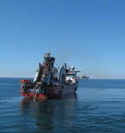
Following completion of the pipe coating, all the three-layer and four-layer coated pipes were delivered to Subsea 7’s North Sea spool base in Norway. Subsea 7 conducted the pipeline assembly, reeling, and offshore installation.
As a result of the testing prior to pipelay, the pipeline has been laid successfully and is fully operational. The pipeline works in conjunction with existing infrastructure to facilitate the safe transportation of gas from seabed to the shore.
Offshore Articles Archives
View Oil and Gas Articles on PennEnergy.com


