Industry aims to consolidate number of umbilicals
Larry Forster
Mac McKee
INTECSEA
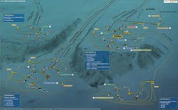
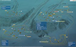
This year, the poster has a new graphic to show subsea processing equipment in field layouts and illustrate several configurations possible with ever more advanced technology. We have endeavored to show multiple types of subsea processing components and subsystems in hypothetical, yet realistic field configurations.
For this article, Configurations 3A and 3B were extracted from the poster. It shows a three phase separation system, gas compression and liquid boosting to the host platform, and treatment of produced water via an inline separator to provide one of two optional sources for injection water. The second option for injection uses filtered seawater.
The graphic shows two additional subsea configurations, starting with Configuration 1, Basic Three Phase Boosting, and Configuration 2, Subsea Two Phase Separation and Two Phase Boosting. These configurations are also useful to illustrate the application of particular subsea processing systems and components. Also included are callout references to assist in tying the various examples of components pictured elsewhere in the poster, to particular locations in Configurations 1, 2, and 3.
Configuration drivers
From the outset, subsea processing has been envisioned as ultimately replacing the topsides facility associated with subsea fields. Operators and manufacturers who are taking a systems approach are well on the way to achieving this vision. One advantage of the systems approach is becoming visible in the architecture depicted in the image. The modular nature of subsea processing components and subsystems results in seabed equipment configurations in tune with the needs of producing reservoirs and existing infrastructure. For example, water injection modules can be placed in the vicinity of existing drill centers and tied in with relatively short infield flowlines and electrical cables to the remainder of the facility, rather than distributing water lines and cables either from the host or from a centralized subsea station. These water injection modules might incorporate re-injection of produced water, injection of filtered seawater, or both.
Other equipment modules can also be readily added to the seabed where needed and when needed, without the unneeded cost, disruption, and risk of reworking space-limited topsides facilities. Gas compression is another prime example of this flexibility in design brought about by recent subsea processing technology advances. For a typical oil dominated field, where associated gas is not present in significant volumes early in field life, or for a typical gas dominated field where pressure decline is not an issue until a few years into production, gas compression modules can be slotted into existing subsea field architecture following production start-up. When combined with standardized, networked controls and subsea power distribution, subsea systems become easily adaptable to the complex changes needed over field life. This is analogous to adding wells to existing subsea manifolds.
Consolidation of umbilicals
While the image represents current thinking and practice, at least one aspect of the architecture is likely to evolve - and soon. The poster graphic shows three separate umbilicals: for production controls and chemical supply, for processing system controls, and for supply of power. The next key step in subsea system design will be to consolidate these three separate umbilicals into a single common umbilical for all needs. Capital cost reduction through reduction of the umbilical count is the primary advantage of this consolidation. However, further consolidations in the subsea architecture are expected to follow, leading to a self-contained, self-sufficient, and simplified subsea facility.
The first of these consolidations will involve structuring the controls and associated data communications systems into a networked arrangement, with industry standard internet protocols and fiber-optic communications. Key suppliers already have a head start in this new architecture. These new self-contained subsea systems will then align naturally with the topsides facilities, whose operation has already migrated to remote and efficient operations and surveillance centers, often adjacent to or within the corporate offices of operating companies.
Electrical distribution
Subsea electrical distribution is also a key part of the new subsea system architecture addressed above, and even more emphasis and detail will be forthcoming in future poster editions. While the concept of a single umbilical to the subsea system simplifies the overall system concept, the associated subsea electrical distribution system will be highly complex. The high number of components and the accompanying interconnections give credence to the LEGO-block concept of modular packaging among the components currently advocated by Statoil and others. The industry-standard protocols mentioned above in reference to control and communications are also key elements to ensuring the electrical systems are manageable as well as reliable.
System highlights
The 2016 edition of the poster emphasizes system applications, so that details on individual components may be viewed within the overall context. Not enough can be said about the importance of the systems approach in ensuring successful installations, and success over the entire field life. Speaking of successes, there are several to recognize this year including: the startups of the Åsgard and Gullfaks subsea compression systems, boosting systems at the Chevron Jack/St. Malo field in the US Gulf of Mexico (fully commissioned, ready for startup), the Total Giri field in block 17 offshore Angola, and the Repsol Montanazo field in the Mediterranean.
Technology highlights
Successful systems are supported by sound and successful components. Developments continue in 2016 in the system components from established providers, new providers, and new strategic partnerships. Highlights of these activities include the award to FMC Technologies for a multi-phase pumping system to be installed at Shell’s BC-10 field in Brazil, a first product installation for the FMCTI/Sulzer exclusive collaboration agreement in pump manufacturing. In 2015, Aker Solutions and MAN Diesel & Turbo formed an alliance to develop next-generation subsea compression systems, based on the successful delivery at Åsgard. Also in 2015, Fuglesangs Subsea AS and the German pump company RuhRPumpen announced a collaborative agreement to develop advanced subsea centrifugal pump solutions. GE Oil & Gas recently formed a joint industry project, involving several oil and gas operating companies, to develop a smaller, simplified, lower cost subsea boosting system based on technology from the GE Aviation business. Both GE Oil & Gas and Fugelsangs Subsea AS are targeting elimination of the requirement for barrier fluid systems in their pump designs. Finally, Aker Solutions and Fjords Processing also formed an alliance last year to develop technology for advanced, cost-effective wellstream separation and treatment solutions.
New alliances
As a final note, in 2015 the industry witnessed the emergence of a new type of company or business arrangement, which was dubbed “Integrated System/Installation Strategic Partnerships” in the Supplier Matrix section of the poster. The first of these partnerships, Forsys Subsea, is between FMC Technologies and Technip. The second partnership is between OneSubsea and Subsea 7. Finally, Aker Solutions and Saipem announced their new partnership in December 2015. As part of the announcement, Aker Solutions CEO Luis Araujo said: “We will team up with Saipem on target projects, providing integrated solutions that will enable our clients to make the most of their upstream investments, reduce development time, and lower operating costs.”
More integrated system partnerships are expected in the near future, once again reinforcing the emphasis on “tying it all together.”
