Detailed crane analysis critical to platform life extension, decommissioning
Regular inspections needed to combat fatigue, damage, and corrosion
Stuart Smith
Brendan Forbes
Sparrows Group
Understanding structural fatigue in offshore cranes and their overall condition is necessary to safeguard the integrity of deck operations and to comply with safety requirements. It may also prove to be critical as many of these cranes and their components are yet to enter the toughest stage of their life cycle.
During the decommissioning of platforms, the demands placed on offshore cranes can be greatest at the very end of their working lives.
In the past, it was common practice to change out a crane’s structural components on a five-year cycle to ensure their integrity. This typically involved removing and lowering the boom, an operation which would take up a great deal of deck space and hamper or even halt work altogether on the platform over the two- to three-week maintenance period. The industry now places more importance on understanding the condition of offshore cranes and how they are deteriorating, rather than changing the components on a fixed-term basis.
To comply with the UK continental shelf’s Key Performance 4 (KP4) requirements on managing aging offshore installations, operators must demonstrate they are monitoring their assets effectively. Fatigue analysis is a tool that supports them in this work.
The occurrence of fatigue varies widely between different makes of cranes. Some are extremely robust and rarely experience any failures, even with high frequency of use, due to their low stress range. With other models where the structure is working harder, or where there are susceptible connection details, signs of structural fatigue can appear much earlier.
Many of the first-generation cranes were originally designed as onshore crawler cranes and then adapted for work offshore, used for sea loading and dynamic work. It is not uncommon to find early signs of fatigue on some lighter models of the older first- and second-generation offshore cranes, as these were designed to earlier editions of offshore crane codes with less stringent strength requirements than those that operate today.
On the other hand, there are some robustly designed cranes of this era which exhibit good fatigue resistance. In the second generation of cranes that were designed specifically for offshore use, models from Liebherr and Stothert and Pitts have proven to be extremely sturdy and in many cases have shown little in the way of fatigue.
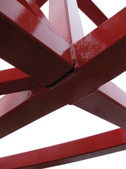
In around 95% of cases, the boom is the section of the structure most vulnerable to fatigue, with its mid-sections particularly sensitive to premature aging. The exception can be the A-frame, which can also have a shorter than predicted lifespan.
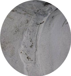
It is not possible to prevent fatigue, but understanding its causes enables operators to guard against its effects. Invariably, welds on the structure are where issues begin. Undetectable flaws occurring during the welding process mean that every weld has a potential defect that could present a weakness in the future. Full penetration welds tend to perform better than the more common fillet welds on the boom’s mid-sections. However, when considering the head and foot boom sections there comes a point where tapering causes the geometry of the lattice chord connection to reduce vastly due to concentrated stress.
In some instances platework stiffeners have been added to strengthen the structure. This can have a positive impact although it also introduces high stress concentration factors that create further fatigue sensitive positions and can lead to an earlier failure of the joint.
The only way to fully understand the condition of the crane is to conduct a study examining loads and cycles. Typically, the average lifted load offshore does not stray significantly from 3.2 metric tons (3.5 tons), with a variance of 0.75 metric tons (0.82 tons).
Although the weight of the load does play a part in the analysis, it is more pertinent to study the stress range. Calculating the difference between the existing residual strain on the structure, the added stress during an actual lift and the spare lifting capacity provides an accurate picture of the fatigue experienced.
Because of the relatively low average load, the number of lift cycles has a greater impact on the fatigue life of the structure than the lifted load itself. This also means there are many large capacity cranes operating at a fraction of their design limits. Lower stress ranges provide longer fatigue lives and occasional lifts at maximum capacity will not significantly affect their fatigue life.
Cranes that operate predominately toward the outer regions of their radius range are more prone to greater stress ranges and therefore reduced fatigue life compared to those operating at closer ranges. All of this can be plotted on an S/N curve with fatigue strength and the number of cycles along each axis, with the Miner’s Rule then applied to calculate the damage through variable stress ranges.
A critical part of analyzing fatigue is determining an accurate life cycle. In the majority of cases gaining reliable information to determine the crane’s life cycle can be a challenge. Many of today’s cranes have a recording load indicator system with a full history of each lift, detailing the weight and the position of the crane when this took place. However, numerous older cranes will not have this information, or if they do, it will only be available for a small proportion of the crane’s life.
It is still possible to establish realistic life cycles for any offshore platform crane even without a recording load indicator system. Knowing the type of work, when drilling programs have taken place, and even the deck layout all make it possible to establish the likely lifting frequency, average weights involved, and where loads were being moved to and from.
Second-generation cranes were designed to perform 500,000 lifting cycles, while the more recent fourth-generation cranes are expected to carry out half that number. In most cases the cranes will not have been used as often as initially expected, with the nature of operations meaning that they tend to be exerted more in bursts of activity followed by quieter periods. During the crane’s first year in service it will be used heavily to assist in the building of the platform before taking on a steadier flow of work that will increase around drilling programs and again at decommissioning.
Sparrows Group has a 40-year track record of working on the UK continental shelf before all lifts were recorded. The company’s knowledge of operating requirements and shipping methods has allowed it to develop an approach to establish realistic life cycles.
Of course, fatigue is only one aspect of a crane’s condition monitoring. The effects of damage and corrosion also play a major part in determining its condition, hence the need for regular inspection. However, accurate fatigue analysis will only highlight the vulnerable areas on the crane. Once these have been established it is important to perform inspections of these areas focusing on the sections prone to fatigue and then increase the inspection rate if fatigue signs are present.
Inspection of crane structures is mainly performed visually or via magnetic particle inspection. Other forms of study such as eddy-current and ultrasonic testing tend only to be viable on small targeted areas of the crane.
So, what happens if fatigue failure occurs? The next step is to take the analysis further and establish a criticality assessment. This involves a stress analysis of the crane that takes into account the potential fatigue failures to determine how this could affect the structure. It may be that if a single weld failure occurs, an alternative load path could be available through the unit and increased use will not cause yielding or further damage. Alternatively, complete structural failure may be the predicted result.
This type of information is especially important to offshore asset owners when making decisions on continued use of aging cranes, particularly when considering life extensions for a facility or decommissioning. During a life extension program, the predicted life of the platform will be compared to the crane analysis and condition reports to establish the options for and risks of continued use.
During a decommissioning program, the crane often has to perform vastly increased operating cycles with heavier loads when it may already have exceeded its designed operating life. It is not unusual for asset owners to replace or change-out cranes before embarking on such projects in order to lessen the risk of reliability issues or structural failures. Equally, this analysis can provide assurance that continued use during this highly active period of the crane’s life can be conducted without concern, with the crane safe to operate over the asset’s full working life. •
The authors
Stuart Smith is global design services manager for Sparrows Group. He has been employed in the firm’s engineering department for the duration of his 22-year career specializing in the design and analysis of lifting equipment.
Brendan Forbes is global head of engineering at Sparrows Group based in Aberdeen, UK. He holds a BSc in Engineering and Management from Edinburgh’s Heriot-Watt University and holds professional accreditation with the Institution of Mechanical Engineers and Society of Operations Engineers.
