Brian Green
Severn Subsea Technologies Ltd.
Conventional high integrity pressure protection systems (HIPPS) for emergency shutdown ofsubseapipelines rely on complex electronics and instrumentation. However, questions over the reliability of electronic HIPPS have restricted their use, especially in the Gulf of Mexico. The development of a mechanical HIPPS addresses some of the issues associated with conventional instrumented HIPPS.
High integrity pressure protection technology has been the subject of detailed evaluation for many years, with subsea applications under intense scrutiny from operators and environmental authorities in many parts of the world. There are a number of issues associated with current, electronically instrumented HIPPS. The first is cost. The second is perceived reliability problems. Hydrate formation inside pipelines, for example, has been known to affect pressure sensors, and resulted in installed systems failing to function during periodic testing.
The third is the range of potential emergency shutdown scenarios in systems where programmable logic controls are used – specifically, that they cannot be fully tested and evaluated, a point which is highlighted within guidance notes to IEC61508. There are also commercial and project issues stemming from the bespoke nature of each HIPPS deployment, the required configuration time, and the need for high caliber engineering resources, which can impact project schedules.
The mechanical HIPPS is designed to reduce the complexity of current HIPPS technology and provide a cost-effective, reliable subsea and topside alternative to the current instrumented systems. It also tackles the issues of wax deposition and hydrate formation, which presently may limit HIPPS performance.
Mechanical HIPPS
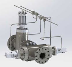
The mechanical HIPPS is essentially an isolation valve with high integrity controls that provides pressure protection up to the level required for the project. It uses hydraulics to achieve a highly accurate and reliable pipeline valve emergency shutdown controls capability, which contrasts sharply with existing highly complex electronic, instrument-based pressure protection systems. Moreover, the hydraulic HIPPS provides a complete pressure protection unit, as opposed to a set of component parts that require configuration and engineering for each new application.
The technology can be used to provide isolation in the event of a system or pipeline breach, monitoring and responding to differential pressure along a section of pipeline. It can also be installed in remote locations and, if necessary, with no supporting infrastructure, while still maintaining up to SIL 3 protection.
The SIL 3 mechanical HIPPS comprises two pipeline isolation valves, each controlled by two independent hydraulic control sub-systems. The valves are arranged in series within the pipeline, with each capable of independently isolating the flow when closed.
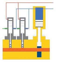
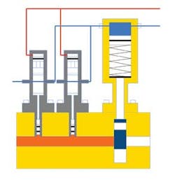
The HIPPS valve is controlled by two hydraulic control cells, each of which acts as an independent means of trip-closing the valve. The control cell is a bidirectional pilot-operated valve that balances the pipeline pressure against a reference pressure. It is independent, and provides system redundancy and a calculated unit reliability rating of SIL 2. When two mechanical HIPPS valves are positioned in series, the reliability rating is increased to SIL 3.
In normal operation, the reference pressure exerts a greater force on the pilot valve (due to a combination of pressure and piston head area) than that created by the pipeline pressure, maintaining the pilot valve in the closed position. The HIPPS valves remain open, since dumping of their control fluid is prevented by the closed pilot valves.
In the event of pipeline overpressure (typically 85% to 95% of pipeline maximum operating pressure), the force developed on the control cell pilot valve by the pipeline pressure will exceed that produced by the reference pressure, and the control cells will move to the dump position. This will vent the hydraulic control fluid from the HIPPS valve actuators, allowing them to close under integral spring force, thereby isolating the upstream section of the pipeline from the downstream.
Because control is provided by a small-bore subsea valve, as opposed to DCV-based instrumented controls in conventional HIPPS, it is possible to achieve rapid closing, with a flow of up to 18 liters per second venting down the pipeline isolation valve actuator. Similar closing times can only be achieved with conventional instrumented systems by introducing a small-bore valve in the same configuration but controlled by a DCV; however, this compromises the reliability calculations, making it difficult to achieve even SIL 2 reliability levels.
Following an over-pressure event, when the pipeline pressure reduces below the reset pressure, the hydraulic control cells will return to the closed position. It then becomes possible to control the isolation valves again, using the production control system, and to restore each valve to the open position in order to resume flow.
Extensive testing
The mechanical HIPPS has been subjected to extensive performance and qualification testing with long-term hold tests, rapid cycling, and accuracy tests, with data logged from more than 6,500 simulated over-pressure events. In addition, a comparison has been made between the mechanical controls and conventional instrumented HIPPS and their performance under adverse conditions, such as where hydrate or heavy wax deposits form in the pipeline.
Testing shows that the control cell's operation is more robust. Mechanically, the area exposed to pipeline pressure is more than six times the surface area of a conventional subsea pressure transducer's diaphragm, hence its ability to operate accurately is significantly less likely to be impaired by hydrate and heavy wax deposits. Control cells have performed reliably and achieved high levels of accuracy and repeatability, with a performance tolerance verified at +/- 0.65% of the required trip pressure.
The conclusions of testing, reliability calculations, and comparisons to existing instrumented HIPPS are encouraging. Topside mechanical HIPPS technology has existed for some years now, but this is the first mechanical system which can also be used insubsea applications, and it is therefore natural to make comparisons between the two. In practical terms, the achievable trip accuracy of mechanical HIPPS compares well with instrumented HIPPS. However, basic mechanical principles suggest that any long-term drift in operating accuracy would not be possible due to the forces being applied to the control cell during an over pressure event that massively outweighs the modest force actually required to trip the control cell and trigger an emergency shutdown. This sustained accuracy was demonstrated throughout qualification testing.
Reliability calculations, conducted by an accredited third party, established sufficiently low probability of failure on demand (PFD) figures to conclude a high-end SIL 3 capability where, in the unlikely event of a single control cell failing within a dual isolation valve SIL 3 configuration, the system could continue to operate with a SIL 3 reliability status, albeit at the low end of the SIL 3 PFD range. This is potentially a major advantage in circumstances where a problem becomes evident during periodic testing. It could allow the operator to take a structured approach to resolving the issue while maintaining full SIL 3 pressure protection, as opposed to defaulting immediately to a shutdown and suffering potential production losses if the repair requires intervention.
Remote HIPPS
Mechanical HIPPS offers high integrity protection in remote, unsupported subsea or topside locations, where there are no monitoring or utilities available, and therefore beyond the reach of conventional HIPPS. For example, where a well is to be produced via a tieback arrangement, the well may have a slightly higher wellhead shut-in pressure than the surrounding flowline infrastructure. By using the two mechanical HIPPS in the flowline adjacent to the new tree, all of the flowline downstream of the hydraulic HIPPS valves can be de-rated along with the surrounding infrastructure. The cost of deploying an instrumented HIPPS for the same application could be prohibitive, preventing the well from being developed.
Where pressure protection is needed in a remote area and there is no supporting infrastructure whatsoever, HIPPS can be installed in the fully rated section of the pipeline, and an accumulation module used to provide the reference pressure. Although, in system terms, the accumulation module then forms a part of the HIPPS, it does not form part of the system reliability level calculation. Therefore, even in a remote installation such as this, SIL 3 is achievable. This kind of system arrangement will require periodic testing, which can be conducted from a surface vessel.
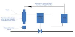
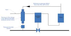
In a pipeline breach monitoring application, the control cell takes references from upstream and downstream of an isolation valve and responds to any predetermined level of differential pressure by tripping and closing the isolation valve. This limits environmental damage to the volume of hydrocarbons in the pipeline between the two isolation valves.
Small mechanical HIPPS valves can also be used to support conventional instrumented HIPPS, providing cost-effective high integrity protection on bypass lines. Support for conventional instrumented HIPPS can also be provided using hydraulic HIPPS valves in a parallel, "layered" arrangement, with increased reliability due to reduced potential common modes of failure.
Looking forward, the versatility and relatively low cost of hydraulic HIPPS valves offers the oil and gas industry a means of protecting systems from overpressure in both drilling and production. The mechanical HIPPS valve is as near to an off-the-shelf solution as possible, and in essence removes all potential instrument-related reliability issues. It provides a relatively low-cost, effective solution when compared to existing instrumented high integrity controls and pressure protection solutions.
