Renaud Gueret
Subhajit Lahiri
Subsea 7
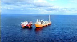
Total E&P UK and partner DONG E&P (UK) are developing theLaggan and Tormore gas fields, 127 km (79 mi) northwest of the Shetland Islands. This is the longest and deepest-water subsea-to-beach project in UK waters.
In summer 2012,Subsea 7 installed a 127-km (79-mi) umbilical between the landfall on the northern shore of the Shetlands and the Laggan subsea manifold. This was configured as a bundle, including two-way fiber-optic communication, high-voltage electricity supply, chemical supply, and hydraulic power. Installation involved laying a low-density product (127-mm [5-in.] diameter and 10.6 kg/m [23.4 lb/3.28 ft] submerged weight) along a route with high currents and water depths of 20-600 m (65.6-1,968 ft).
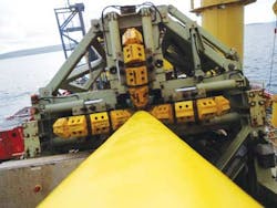
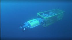
Large umbilical deflections were foreseen, so asubsea depressor device (SDD) was developed to assist installation and to act as ballast, weighing down the catenary and opposing the current. This was the third project in which the company had used this device, but twice as large as the two previous applications. It comprised a weight element with a bellmouth funnel opening on each side through which the umbilical was run and suspended from deck winch. The wire length was adjusted to control the height of the SDD above the seafloor.
Laggan and Tormore are in blocks 206/1a (license P911) and 205/5a (P1159). The development calls for a long-distance tieback of subsea wells connected to a new gas processing terminal at Sullom Voe on the main Shetland island, with the processed gas exported southeast via a new pipeline that connects to UK's Frigg (FUKA) trunkline system. The wells will be controlled via the electro-hydraulic umbilical.
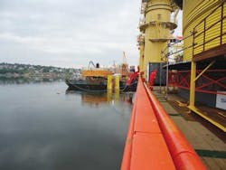
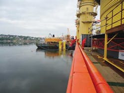
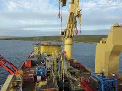
The lay route from Orka Beach passes through the Yell Sound bay where theNormand Oceanic construction vessel was relatively sheltered from the waves. Water depths along this section started at 20 m (65.6 ft), at the location of the beach pull-in, to roughly 90 m (295 ft) at the transition to open sea. The depressor was first deployed a couple of kilometers from shore in 40 m (131 ft) of water. In the Yell Sound bay the route passed close to some islets where tidal currents reach up to 4 knots, and are fast-changing both in intensity and direction.
From the outlet of the bay, the water depth increased from 95 m to 600 m (311 ft to 1,968 ft). The current veered from a tidal pattern to a more constant oceanic current, reaching a one-year return period value of 1.41 m/s (4.6 ft/s) at Laggan (sea surface current). It also became very directional, coming from the southwest, almost orthoganal to the lay route, and fluctuating much less over time.
Design current speed
Early results confirmed that installation of the umbilical under the one-year current was difficult. For that reason it was important to select acceptable current speeds from the available environmental data. The extreme current likely to be encountered offshore was then determined, and following a sensitivity analysis, the umbilical configuration was altered significantly for more moderate currents expected 80% of the time. Finally, scaling factors were applied to the design currents based on their directions; the design current against lay - the most adverse for installations in deepwater - was significantly reduced. The current selections were translated into matrices defining design current intensities, and formed the basis of the environmental input for the analysis (strong and moderate currents). Fifteen locations along the lay route were selected for the analysis corresponding to the points where metocean data were available.
In Yell Sound bay, 75% of the omni-directional, one-year current intensity was applied for the strong current matrix, whatever the direction of the current. For the moderate current matrix, the threshold speed was reduced to 50% of the one-year return period current speed. For locations close to islets in this area, the current was very directional, orientated north/south. Cross-current is of a much smaller magnitude, so 30% of the one-year return current was applied for the strong current matrix and 25% for the moderate current matrix.
Analysis of environmental statistics for locations farther offshore suggested a small chance of significant current intensity in the lay direction or against the lay direction. For the strong current case, current intensity of 40% of the one-year return period current was selected, while a 30% current intensity was chosen for the moderate case. For the strong orthogonal current scenario, 70% of the one-year current was adopted.
Stiffness considerations
Although the umbilical's submerged weight is similar to that of similarly dimensioned umbilicals laid in previous deepwater projects in comparable conditions (i.e. Ormen Lange in the Norwegian Sea), the bending stiffness is significantly higher.
Under extreme environmental conditions, the umbilical lay depended on the use of a subsea depressor device (SDD), comprising a weight element with a bellmouth funnel opening on each side through which the umbilical was run. The 2.5-metric ton (2.7-ton) SSD was ballasted with steel blocks to boost its weight to 4.6 metric tons (5 tons) to deal with the unusually high currents. A quarter section of the depressor is hinged and can be opened to allow umbilical entry or exit during the installation. Its lashing mechanism can operated via an ROV for opening and closing at depth.
The SSD was suspended from a deck winch via two bundles connected close to the center of gravity. It was free to pivot around its axis and to follow the umbilical's natural curve. The deck winch wire length was tuned to control the unit's height above the seafloor, acting as a ballast to weight down the catenary and to pull it back toward the vessel to oppose the current effect.
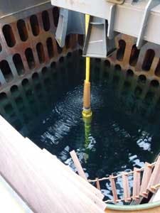
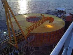
The umbilical was stored at the vessel's stern on a 24-m (79-ft) wide deck carousel with a 3,000-metric ton (3,307-ton) capacity. The lay system comprised an under-bender roller chute to guide the umbilical into the 300-metric ton (330-ton) tensioner entry aligner and a compensator, placed between these two components to maintain hold-back tension at a suitable threshold. Finally, an over-boarding chute was placed at the tensioner exit to guide the umbilical over the vessel moonpool.
For the first phase of the umbilical installation, at the landfall at Orka Voe, the umbilical was pulled through a 512-m (1,680-ft) long subsea conduit up to the beach where it was tied to the connection pit. The installation vessel was positioned parallel to the shore, with the tensioner exit 30 m (98.4 ft) from the conduit entry bellmouth. The onshore winch was retrieved onboard and connected to the umbilical pull head, and the latter was over-boarded and lowered to the seafloor before being pulled through the conduit.
Prior to starting any operation the vessel was engaged for three days of surveying the bay and measuring current along the lay route. Over the initial shallow section, zones of strong currents were identified with speeds of up to 4.6 knots, alternating with sheltered areas. Those velocities exceeded the 2.5 knots maximum predicted by the tidal atlas, and were caused by semi-diurnal tides with 12-hour periods. A lay strategy was adopted to position the vessel a couple of hundred meters away from a strong current zone in a sheltered area, waiting for the tidal current to abate before resuming the installation. Umbilical lay then continued up to the next zone of high current before repeating the process.
Once water depths reached 40 m (131 ft) the depressor could be deployed to stabilize the umbilical and to allow laying to be performed accurately, to a precision of within 1 m (3.28 ft), and without interruption. Weather was benign and the vessel motion moderate, so no whipping effect occurred at the touch-down point. The depressor's height was maintained at 20 m (65.6 ft) above the seafloor throughout the entire lay operation. This was shown to be optimal both for lay accuracy, and for preventing the umbilical from being dragged away from the vessel.
As the water depth increased, the umbilical offered more sail area to the current and umbilical drag started to increase. This necessitated offsetting the vessel from the route to maintain the touchdown point. Tables were prepared for water depths ranging from 40-600 m (131-1,968 ft) to determine allowable vessel layback and the required offset in weak, moderate, and strong currents. The cross-current cases corresponded to higher current velocities as these had a much large probability of occurrence.
A storm contingency was made that would secure the umbilical in a lazy S-wave configuration using buoyancy modules. The SDD would then be connected at a height of around 40 m (131 ft) above the seafloor, in water depths of 90 m (295 ft), and 60 m (197 ft) above the seafloor in water depths beyond 120 m (393 ft). During installation, the clement meteorological conditions rendered such deployments unnecessary.
This project proved that installation of a lightweight umbilical was feasible in the difficult environment typical of this region, and the subsea depressor proved successful in stabilizing the umbilical motion in the touchdown region and preventing it from being dragged far away from the vessel. Subsea 7 now considers the method its primary option for future such installations.
Acknowledgment
This is an edited version of a paper presented at the SPE Offshore Europe Oil and Gas Conference in Aberdeen, Scotland, in September 2013.
