Electrically heated pipe-in-pipe – A qualified reelable technology to meet flow assurance challenges
Sylvain Denniel
Philippe Bonneau
Pierre-Antoine Savy
Technip
Hydrate and wax plugging often limit subsea tieback distance and deepwater field development, and can make remote oil and gas resource recovery uneconomic or excessively risky.
Maintaining the produced fluids temperature outside the critical hydrate or wax formation zone often can be done using a high-performance passive insulation system such as pipe-in-pipe. However, flow assurance trends suggest that passive insulation alone does not suffice for the development of the most demanding fields or requires added flow assurance strategies involving large amount of chemical inhibitors. To address this, Technip has developed and qualified a reelable electrically heated pipe-in-pipe system (EHPIP). It combines the best available passive insulation technology at atmospheric pressure with safe and reliable electrical trace heating to optimize performance and minimizing potential opex and topside capex.
Pipe-in-pipe is an established technology for deep and ultra deepwater.1,2 It provides unrivalled passive insulation to minimize heat losses to the environment to allow development of deepwater fields with low reservoir temperature, wax or hydrate risk, or those remote from topside infrastructure.
To meet increasingly stringent flow assurance requirements, a natural extension to reelable pipe-in-pipe is the addition of active heating. Electrical trace heating, widely used onshore and for some offshore applications, can be applied to an existing reelable pipe-in-pipe system. Electrical heating allows the flowline temperature to be maintained above critical levels, to control warm up, or to extend cool down time. Thus it provides the operator a way to optimize production and reduce risks of blockage. This flexibility can be enhanced further with optical fiber technology, which already is used offshore for real-time flowline temperature profile monitoring.
General description
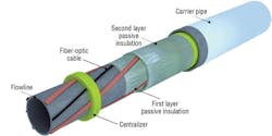
The EHPIP is a standard reelable pipe-in-pipe system to which Technip has added a trace heating system between the flowline wall and the thermal insulation for optimum efficiency.
The EHPIP system can be divided into three main parts:
• The pipe-in-pipe itself, comprising of standard components such as high performance insulation and structural polyamide centralizers (with slots to accommodate passage of cables) but also the trace heating system and an optical monitoring system. The electrical heat is provided by pure Joule resistive effect
• The subsea power feeding arrangement includes a power umbilical and subsea connectors. The umbilical transports electricity and optical signals from the topside to the subsea umbilical termination arrangement (SUTA). The SUTA connects to the EHPIP via flying leads, which in turn connect into wet-mate connectors mounted on tee structures. This tee piece structure provides the interface between the wet pressurized subsea environment and the dry atmospheric pressure pipe-in-pipe annular space. In the case of a field including a flexible riser, it is conceivable that the riser itself is heated and conducts both electrical power and optical fiber to the EHPIP. Technip has installed an integrated production bundle (IPB) in Angola
• The topside control unit together and electrical power production facility. This regulates the power supplied to the cables within the EHPIP by monitoring the temperature of the flowline using optical fibers. Topside control units for similar applications exist for IPB risers.
The trace heating system is based on a three-phase STAR configuration. This means three separate cable cores each conduct one phase of the three-phase current. Each phase meets at the star connection remote end, where the sum of current phases is nil. Consequently, there is no requirement for a return current umbilical.
The base case cable design, on Technip's first subsea EHPIP application is constructed so the three phases (cores) of one system are housed within one outer jacket. In other words, one cable represents one individual trace heating system. Each core is sufficiently insulated to withstand the required system voltage. The entire assembly is enclosed in a braided metallic outer protective layer. This flat, compact cable geometry eases application during the assembly stage, while limiting impact on the overall heat transfer coefficient (OHTC). It also benefits from an optimum contact surface against the heated flowline to maximize heat efficiency and reduce risk of over-heating.
Due to the assembly procedure of a rigid pipeline, it is not possible to apply the trace heating cable in one continuous length. In-line connections are designed to be efficient and safe links between two sections of trace heating cable. Reeling is arguably the easiest installation technique to adapt to trace heating. Assembly and connections are made and tested onshore. Furthermore, the number of in-line connections is reduced (typically every 1 to 1.5 km [0.6 to 0.9 mi], depending on the size of the construction base).
The trace heating system on the first-ever field application of EHPIP is designed for long-term exposure to a design temperature of 120ºC (248ºF) and a phase voltage of 2 kV. One single-cable system is can provide the required heat. As a spare philosophy, more than one cable system can be designed in to provide 100% redundancy per additional cable system. By default, more than one cable will be used conjointly during operation, hence minimizing heat output per cable. Use of a single cable for heating would occur only in the unlikely event all of the other spare cables fail. This unlikely scenario is termed as "degraded mode."
Temperature monitor is by optical fiber. Additional layers can be placed around the fibers for mechanical protection. Optical fibers are used in a number of subsea components such as umbilicals and IPBs. Temperature monitoring is achieved either using distributed temperature sensing (DTS) or fiber Bragg Grating technology (FBG).
Both the base-case design trace heating cables and the optical fibers are applied onto the flowline in a spiral configuration to ensure compatibility with the reeling operations. This involves a spiraling machine integrated within the existing pipe-in-pipe stalk assembly process, with little disruption to fabrication. The spiraling machine arrangement is based on Technip's experience in the manufacture of flexible pipelines and umbilicals.
Applications
A high-performance trace heating system allows an operator to minimize non-productive shut-down times by ensuring efficient warm up, by maintaining the temperature of the line above a critical wax/hydrate level, or by slowing cool down. As a result of the high performance of the passive insulation and the location of the trace heating against the flowline wall, the linear power input necessary to meet the heating requirements is relatively small compared to other systems. This minimizes topside power input or enables heating over greater distances.
The following list summarizes some of the possible applications for the EHPIP concept:
• An alternative to a pigging loop for wax or hydrate mitigation
• Very long tiebacks
• SCR heating to counter temperature drop caused by adiabatic cooling (Joule-Thompson effect). Such application also exists with IPBs
• To complement passive insulation during steady-state operation. This applies especially to heavy oil fields where high wax-appearance temperature (WAT) may force continuous heating for years. The lower opex of EHPIP, associated with both passive and active efficiency is then a significant advantage. Providing long-term continuous and uniform heating is an advantage of EHPIP
• To be used with a downhole electrical submersible pump (ESP), using an electrical subsea switch module (ESSM), to divert the pump's power supply to pipeline heating during shut-in
• To heat short bypass sections, allowing flexibility of field operations.
The passive insulation and active heating performance of an EHPIP is generally project specific and depends on key input parameters including, but limited to target OHTC, target heating temperature, fluid properties, pipeline dimensions and length, and trace heating redundancy policy.
System qualification
A strong basis of the EHPIP design is to maximize the combination of components that have track records in comparable or harsher conditions. For example, Technip has a track record in the design manufacture and reel installation of pipe-in-pipes. Reeling of electrical cables occurs regularly with a power umbilical or IPB, and at tighter radii of curvature than experienced by EHPIP during reel-lay.
Emphasis on manufacture quality and control is equally important and is achieved through the selection of the reeling pipe-lay method. Indeed, manufacture of pipeline stalks is in factory-like environment at the local onshore base, away from the offshore construction critical path. It is possible to introduce many steps of integrity control of both the electrical trace heating and optical monitoring systems. Furthermore, as mentioned, the other advantage of reel-lay is that the manufacturing process cuts the frequency of in-line connections to one every stalk length.
A first qualification program phase was undertaken in 1999-2004. It included the following:
• Review of the full electrical design, including assessment of the electrical integrity of the system, including consideration of induction effect
• Definition of topsides power, control, and monitoring systems and philosophy
• Development and testing of cable lay up arrangement compatible with the reeling process
• Development and trial of EHPIP assembly procedures
• Specification of integrity testing requirements during assembly and installation
• Full scale 8-in. in 14-in. EHPIP joint, including all components of the trace heating system, a T-piece and power connectors was fabricated. The thermal performance, pre- and post-reeling, was established to confirm that the design calculations were accurate. For this, the test piece was submerged in a water tank at a regulated temperature of 4ºC (39ºF) and a flow loop circulated oil through the test piece.
In 2009/2010, a fasttrack qualification campaign was undertaken in partnership with a major operator to further qualify EHPIP for a long-term temperature exposure of 120ºC (248ºF) and with the option to further extend heating ranges by enabling phase voltage applications up to 2 kV. As part of this qualification, it was decided to revisit failure mode identification. A number of activities were then defined to address the issues raised during the system review process. These were packaged into the following activities:
• Preliminary EHPIP design
• Thermal analyses
• Full-scale thermal trial
• Demonstration of long-term integrity through laboratory tests
• T-piece design and assembly
• Electrical design (power feed) and components specification
• Onshore assembly procedure (including testing)
• Offshore installation procedure (including testing)
• Operability and reliability assessment
• Review of thermal monitoring
• Assessment of effect of reeling on heat tracing cables.
Offshore Articles Archives
View Oil and Gas Articles on PennEnergy.com
