By Willem J. Timmermans
Intec Engineering President
PART I: This is the first part in a two-part series. Part I recaps the history of offshore pipelines. Part II is a forecast of the future of offshore pipelines.
From the earliest days of North Sea activity, with 50% downtime, the pipelay industry has been adapting and innovating to meet the challenges of increased water depth and hostile environments.
North Sea experience
Offshore exploration in the North Sea led to the discovery of gas fields off southern England by 1970, and oil had been found at Ekofisk. Suddenly, the market required long-distance pipelines leading to the UK shore. Even Ekofisk in the Norwegian sector of the North Sea needed a UK destination because the Norwegian Trench was considered an obstacle that no 1970s method or equipment could overcome.
Offshore pipeline design and construction had already come of age in many other places. Specialized pipelay barges were active in the Gulf of Mexico, off Southeast Asia, and in the Persian Gulf. Bottom-pull installations of more than 30 km length had already been accomplished. So it was with considerable experience that the offshore pipeline industry attacked the North Sea, only to find it was a different world.
Unique environment
The climate in the North Sea turned out to be more severe than experienced elsewhere. For that reason, the flat-top laybarges proved inadequate. Their prod- uctivity was very low, and their delicate stingers became consumable items. In spite of these problems, contractors were able to make money. They were paid for weather downtime, equipment failure, and wet buckles. This drove up costs, and the free market dictated this could not last. More cost-effective solutions were needed. Researchers worked to develop and test ways to safely and efficiently design and install pipe in depths exceeding 100 m. In a rare instance of identifying a problem before it happens, the Battelle Institute in Ohio, USA, discovered in 1970 the buckle propagation phenomenon and developed the buckle arrestor.
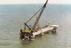
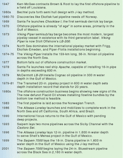
This innovation shows how, three and four decades ago, the industry recognized that new methods and approaches would be required for future developments in deeper water and more hostile environments. In the mid-1960s, Shell awarded Bechtel a $1 million contract to develop new pipelay methods and techniques. The Bechtel study identified the potential of the semisubmersible hull form and the J-lay method. By 1969, Offshore Technology Con-ference papers described new engineering methods and barge designs. One design showed an inclined ramp between two barge-shaped pontoons that resembled the 1978-build Castoro Sei. Also in 1969, Santa Fe Construction launched the Choctaw I as the first semisubmersible derrick-laybarge. Designed to pass through the Panama Canal, the vessel proved too narrow to be an effective crane vessel. Still, its service in the North Sea as a pipelay barge demonstrated the benefits of the semisubmersible for that environment, resulting in larger versions being built later.
Experiments, progress in the '70s
In 1970, BP conducted tests in the Mediter-ranean Sea to test installation methods for a 32-in. pipe in 130 m water depth. This was in anticipation of the Forties pipeline in the North Sea. When the 110-mile long Forties oil pipeline was actually completed in 1973, it took three laybarges a season and a half. They experienced three wet buckles and 13 stinger failures and had downtime of 50% in one year and 75% the other. The trenching of the line also took two seasons with two large jet barges working inefficiently and at great expense.
Several more large-diameter pipeline projects were started in the North Sea in 1974. North Sea activity dominated the international pipeline scene. That year saw the start of construction of the 730-km, 32-in. Frigg gas lines in the then-extreme depth of 155 m. In 1974, construction of the 440-km, 36-in. Ekofisk-to-Emden gas line across the North Sea into Germany began, as did the 216-km, 30-in. Piper oil pipeline across the North Sea to Flotta in the Orkney Islands in 145 m water depth.
Laying efficiency gradually improved with experience. More robust vessels entered the scene. ETPM launched its 1601 in 1974 and put it to work on the Frigg project. This application showed the advantage of sheer vessel size. In the same year, Santa Fe Construction brought the Choctaw I and Choctaw II to the North Sea, benefiting from the much improved seakeeping abilities of the semis. These vessels were named second generation to distinguish them from the flat-top Gulf of Mexico barges. Despite these improvements, the Frigg pipeline installation still required three seasons and three laybarges with an average uptime of 48%, and two trench barges with an uptime of 46%.
Entrepreneurs recognized the market potential of improved equipment capabilities, and they went to work. Several tanker hulls were converted into large displacement laying and derrick barges, resulting in vessels like the NOC Blue Whale and Sea Lion. The Viking Piper semisubmersible laybarge concept was developed in 1973. The Viking Piper became the largest and most modern lay vessel in existence, designed to lay the mother of all pipelines: a 36-in. pipe across the dreaded Norwegian Trench. The Norwegian government thought the project was too risky despite studies in 1972 that demonstrated the line was a feasible proposition. It wasn't until 1983 that this feat was finally accomplished.
Beefing up vessels
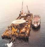
The dismal performance of the available equipment in the late '60s and early '70s pointed out the need for vessels capable of withstanding higher currents and laying pipe at a faster rate. ETPM introduced the double jointing idea and a large displacement ship-shape hull, which raised productivity and reduced weather downtime. Santa Fe showed how semi hulls gave superior stability in rough seas, although they were otherwise quite conventional. The Viking Piper combined the advantages of double-jointing, hull shape, and displacement in a vessel with a length of 162 m, a width of 60 m, and a work deck 13.2 m above sea level. This became the first of the third generation laybarges. The original concept had a number of other features that were judged too far ahead of their time, such as octuple jointing and the docking of pipe haul vessels inside the lay vessel hull.
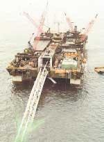
Industry visionaries later picked up on those ideas. The Viking Piper, now the LB-200, boasted a novel feature with its stern ramp, a complete departure from the floating stinger concept that had caused so much downtime in the North Sea. The idea of a 100-m long completely rigid curved appendage at the end of this giant vessel did not strike everyone in the industry as sane. After the LB-200 was damaged in a storm a few years ago, engineers working with the vessel had to be reminded that project members had initially predicted a three-year life expectancy for the vessel, suggesting that its survival for more than 20 years was nothing short of a miracle.
Industry growth
Several consortia emerged. One of these, initiated by Shell, Esso, and Zapata, started what became the Semac-1, which began constructing the Far-north Liquids and Associated Gas Gathering System (FLAGGS) pipeline in 1975. This line was laid in the North Sea from the Brent area to Scotland. The Semac-1 was the second major semi, although a bit more modestly sized than the Viking Piper. Another consortium was formed by Brown and Root, Oceanics, and Sedco. After ordering hull steel and major equipment, the consortium dissolved. Brown and Root decided to go it alone and built the BAR-347. After almost sinking in transit to the Gulf of Mexico, the rig installed a few pipelines with some difficulty. It was then transported to Southeast Asia.
By 1976, several major laying vessels were added to the North Sea fleet, and pipeline installation had become more efficient and less costly. The Viking Piper installed the 159-km long, 36-in. Ninian oil pipeline in 1974 and 1975, requiring only a season and a half. Unfortu-nately, shortly thereafter the bottom fell out of the offshore construction market, and many of those vessels went idle or were used as flotels. One exception was a quiet project in the Mediterranean where Saipem was gearing up for gas pipeline crossings between Tunisia and Sicily. With that major project assured, Saipem had been building the Castoro Sei, and in 1976 the company conducted lay tests with one of its conventional vessels to test procedures and methods in the then unbelievable 600 m water depth. The execution of that 20-in. Transmed project between 1979-1981 set a depth-diameter record that stood for 20 years.
As busy as 1970-1976 was, the late 1970s were uncomfortably quiet. Prices fell and contracts became less lucrative. Shell announced with pride that for installation of the Brent oil pipeline, they paid less for downtime than for working time, and the contractor now handled costs associated with wet buckles.
Meanwhile, in the Gulf of Mexico, the pipeline industry marched on. ETPM installed a 48-in. pipeline from the Louisiana Offshore Oil Port terminal to shore as well as a 42-in. gas trunkline. In 1978, while laying a 36-in. line in 150 m water depth, a buckle occurred, propagated, and was arrested, as expected.
Going deep
In 1975 Shell started a joint industry program focusing on deepwater pipeline technology. Building on the early studies in the 1960s and its own research in the 1970s, Shell mapped out the tools and methods that would allow the pipeline industry to go deep. The first application of that technology was the Cognac oil pipeline in 300 m water depth in the Mississippi Canyon area of the Gulf of Mexico. All possible methods were considered, and a consultant recommended the bottom tow as having the lowest cost and least risk. However, Shell's Carl Langner convinced McDermott that it would be okay to have a tight overbend curve if the steel properties are known, and McDermott won the bid. The line was installed in 1979 by the LB-29, which later foundered in a typhoon off China.
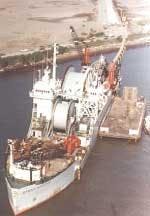
In 1978, Santa Fe Construction launched reel ship Apache, capable of installing up to 16-in. pipe in over 600 m water depths due to its steeply inclined ramp. It was an extension of the reel technology that Fluor Ocean Services introduced many years before with what became known as the Chickasaw reel barge. In the early 1980s, the Apache reeled off the 10-in. and 12-in. lines from the Lena guyed tower in Exxon's Lena Field in the Mississippi Canyon area of the Gulf of Mexico in 300 m water depth at the unheard-of speed of 600 m/hr. It has meanwhile seen several owners and many deepwater pipeline installations, including the Vancouver Island pipeline in 420 m water depths and multiple projects offshore Brazil in water depths approaching 1,000 m.
Booming, busting in the 1980s
By 1980 the industry was booming again, and research and development money was available. Flash-butt welding and electron-beam welding were developed and tested. Deepwater integrated pipeline repair systems were designed, and prototypes were built. It all looked impressive, but little of it was ever used. The cost of these repair systems was higher than the replacement cost of the typically short Gulf of Mexico pipelines, providing little incentive for commercial development. The novel welding techniques encountered resistance from oil companies and unions.
Things were looking up until 1986 when the oil price fell from more than $30/bbl to $10/bbl. Over a few years, more than 500,000 people left the business, never to return. The price drop caused severe economic downturn in places like Houston, Aberdeen, and Stavanger, and major oil companies began downsizing and merging in a trend that doesn't seem to have stopped. It was the time of joint-industry studies. What had been a convenient way to combine industry resources became a means of survival. Deepwater tie-in methods, upheaval buckling, insulated pipelines, and arctic pipeline construction methods were all fair game and resulted in a better understanding of these issues and successful applications later.
Low cost innovation
It became a time for innovative thinking and low cost approaches. Placid Oil installed a number of flowline bundles by the bottom-tow method, and despite some mishaps, the method was shown to be feasible although not the most cost effective. Another Placid Oil first was the freestanding buoyant riser.
In the end, none of this could prevent the company's Green Canyon Block 29 field development from falling victim to a gamble, and Placid Oil disappeared. In 1989, Santa Fe's Apache reel ship won the installation contract for a gas pipeline system near Vancouver, British Columbia, even though bottom tow had been thought to be lower cost in this remote location. Another interesting element in that project was the drilling of curved shafts through hard rock at one of the shore crossings. These were provided with a casing through which the pipe was subsequently pulled as through a J-tube. This idea was later used for the Troll oil pipeline shore crossing at Sture, Norway.
At least one visionary decided to bring a better, faster lay vessel into the market despite all this gloom. This was a fast moving, dynamic-positioned vessel with a lot of pipe storage capacity. The new vessel even had the ability to dock whole pipe haul barges within her hull. The timing could have been better, but the idea clearly was one whose time had come. The Allseas Lorelay entered the world market in 1986. Thanks to considerable speed, she could mobilize to pipeline projects around the world.
Upswings in the 1990s
In the early 1990s, business finally recovered to the point that new projects were again being realized. After 20 years, the focus swung back to the Gulf of Mexico, where serious plans were being made for developments in ever-greater water depths. Shell wanted the Bullwinkle pipeline out to 500 m water depth, followed by the Shell Auger pipelines in over 850 m water depth. It clearly was time to use the J-lay method, which had been originally conceived in the 1960s. The question was whether to convert a drillship or a lay vessel. In 1991-1992, Heerema was the first to use the near-vertical lay system with the installation of a stainless steel clad 20-in. pipeline off New Zealand. Heerema used a J-lay rig mounted on the crane barge Balder. The contract for the Auger lines went to McDermott, which converted the DB-50, a dynamically positioned, ship-shaped vessel built by Challenger Offshore. Saipem laid another two pipelines across the Sicily Channel in 1993 with a beefed-up Castoro Sei.
During the late 1990s, deepwater developments accelerated off Brazil, West Africa, and the Gulf of Mexico. At the same time, long-distance gas transmission lines were designed to cross deep ocean waters. The Shell Mensa project led to the installation by the Allseas Lorelay of a 12-in. pipeline in 1,600 m water depth in the Gulf of Mexico. Newly converted J-lay vessel Saipem 7000 installed the 18-in. Diana pipeline, also in the Gulf of Mexico, in 1999. The same vessel broke the depth record again in 2001 with its installation of the first phase of the Blue Stream project, a 24-in. pipeline across the Black Sea in up to 2,160 m water depth.
Blue Stream benefited from experience gained in the extensive design and testing conducted for the proposed Oman-India pipeline project. Planning on the 1,100-km pipeline traversing the Arabian Sea in 3,500 m water depths halted after design and testing were completed and construction bids were received. Blue Stream demonstrated not only that the Oman-India project was technically feasible, but that responsible construction companies stood ready to execute its installation. During the engineering phase, full scale pipe collapse tests were carried out, welding methods were advanced, and non-destructive testing solutions confirmed. Deepwater route surveys and seabed mapping revealed unexpected features and phenomena requiring solutions. Route surveys were still based on the deep-tow method with its attendant problems of positioning and maneuvering.
Conclusion
The pipelay business is cyclical; it works like a sponge. In every downturn, experienced people get squeezed out, and when things pick up, fresh but inexperienced - and cheaper - resources are soaked up. These cycles make it difficult to maintain a knowledge base and avoid repeating mistakes and reliving the past. Oil companies would benefit from maintaining a body of expertise despite the cycles. Innovation is critical to continued success. Of the major pipelay contractors of 30 years ago, only a few are left. With few exceptions, all existing laying equipment was built in the 1970s. Newcomers have built all the new equipment entering the market since 1970. These new builds make up the current fleet of high-performance vessels. Even if the newcomers didn't survive the downturns, their contributions are evident.
Watch out for the few pipeline engineers whose ideas are termed crazy because they are probably on to something. Dynamic positioning, steel catenary risers, and pipeline plows did not come from traditionalists.
Editor's Note: This is an adaptation of a keynote speech that was delivered at the Offshore Pipeline Technology Conference in Oslo, Norway, in 2000.
