Onshore run-in for offshore process
Chris Dubar, Timothy Forcey, Vaughan Humphreys
BHP Petroleum
Dr. Hans Schmidt
Linde AG
PART II: This is part II of a two part series on Australian LNG. Part I dealt with the advantages of siting an LNG plant offshore, versus onshore, and the processes used in designing the Bayu-Undan plant. Part II involves the cLNG process module, and specifics on the concrete gravity base structure.
The cLNGtrademark Process Module for Bayu-Undan contains the equipment comprising a single train of gas pretreatment (acid gas removal and dehydration), two trains of liquefaction, electricity generation, and other utilities. Studies show that process facilities for the production of two to three million tons of LNG per year can be fabricated in a single process module that weighs about 10,000 tons. Such a module is similar in size to other offshore modules that have been constructed in a number of fabrication yards around the world.
The module is loaded out from the fabrication yard onto a heavy lift barge on multi-wheeled trailers, such as has been done for other modules of similar size.
The process module can then be transported to the gravity base structure (GBS) for installation using the same multi-wheeled trailers used for the load-out. The module is never lifted and is always supported at a number of points. As a result, the amount of structural steel required is much less than on some other large offshore modules.
This method of construction allows for extensive pre-commissioning and testing to be carried out on the completed process module in the fabrication yard, thus, minimizing offshore hook-up and installation.
cLNG reliability
The LNG industry demands a high level of supply reliability, and actual reliability performance of existing plants and design methods have been documented. The cLNG processing plant as designed for Bayu-Undan has been the subject of a detailed reliability, availability, and maintainability (RAM) study, using state-of-the-art computer tools and equipment reliability databases. An average availability of over 96% is expected for the cLNG processing plant itself. This is on par with world-class LNG plants in operation today.Features of the cLNG process that contribute to its high reliability include:
- Relative simplicity of the pretreatment process required for the lean gas produced from Bayu-Undan
- Relative simplicity of the nitrogen cycle liquefaction process, which requires only one main driver
- Provision of dual (2 by 50%) liquefaction trains
- Inherent ability of the cLNG process to maintain LNG production, albeit at reduced capacity, while parts of the nitrogen cycle are shutdown
- Selection of proven equipment provided by vendors with established references
- Rapid maintenance turnarounds possible with aero-derivative gas turbines
- Provision of adequate design margins
- Provision of redundant equipment, such as spare pumps, heat exchangers, power gen eration facilities, and utility equipment.
Gravity base structure
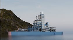
The entire facility for the cLNG facility for Bayu-Undan is supported on a concrete gravity base structure (GBS) which rests directly on the seabed in relatively shallow water (~27 meters). Concrete GBS's have been used for many years in the North Sea and at far greater depths ranging up to 300 meters. More recently, three GBS based production facilities have been installed in Australian waters, two in the Bass Strait (West Tuna and Bream B), and one on the North West Shelf (Wandoo).The GBS required to support the cLNG facilities is relatively simple in design and construction terms, and is heavily-based on proven offshore technology. The simple rectangular cell arrangement is evident. The wave protection wall with wave deflector lip extends above the top slab to deflect extreme waves away from the topsides equipment during the cyclonic storms. The prestressed concrete LNG tanks are constructed on the top slab, which also incorporates the embedment plates as foundations for the other modularized topsides equipment.
At the seabed level, there is an extra buoyancy structure, or "cantilever." This is added to provide the buoyancy necessary to allow the GBS structure, complete with all pre-commissioned topsides equipment, including the LNG tanks, to float out of the casting basin in which it is constructed. Once out of the casting basin and in deeper water, the cantilever is flooded, and the GBS is towed to the offshore site at deeper draught. At the correct location, and in the correct orientation, the GBS is gently flooded down to the seabed. Every cell is flooded, and many cells are then partly filled with iron ore ballast, to ensure adequate weight on the seabed for wave resistance.
Like all offshore structures, the GBS configuration and detail design is heavily dependent on site specific conditions and the construction method. The basis of design data, such as metocean conditions, geotechnical conditions at the proposed site, and seismic criteria have been gathered for this project. The particularly critical design input parameters which govern the overall configuration for such a GBS application are:
- Water depth and tidal range at the offshore location
- Geotechnical conditions at the offshore location
- Casting basin and tow-out channel water depths
- Topsides size and weight for float out and tow to the offshore location.
The potential for LNG to slosh inside the tanks, because of very small movements of the GBS during extreme storms waves, must be considered. As LNG tank construction is critical path, early access to the GBS is required. Fendering and mooring points must be provided for the integral loading terminal. The geometry and strength of these must be suitable to berth standard LNG carriers with standard equipment.
Room is provided on the GBS for future expansion via an additional LNG train, since the GBS offers great capability to support additional topsides equipment. Finally, abandonment of the GBS must be considered - the facility may be removed and possibly re-used at the end of the project life.
LNG storage/offloading
The LNG tanks selected are of the latest design and highest integrity "land-based" type full containment tanks as used for the most recent Japanese tank constructions. They consist of a 9% nickel-steel inner tank and a 800-mm thick, pre-stressed concrete outer tank, with a domed, reinforced concrete roof.These tanks simply sit on the GBS top concrete slab, which is at all times above the waterline. A concrete outer wall was selected based on safety considerations, in order to provide unsurpassed protection from potential external events such as dropped objects and blast over-pressures.
For Bayu-Undan, the storage volume selected is 170,000 cu meters total, in two equal-sized tanks. The outer concrete tank diameter is 66 meters, the inner steel tank diameter is 62 meters, and the wall height is 34 meters.
Offloading of LNG from the storage tanks to standard LNG carriers takes place at the terminal integral to the GBS. This incorporates a steel platform which supports the loading arms at the correct height, a fendering system attached to the side of the GBS, and mooring platforms with quick release hooks and capstan winches. All this equipment is standard and proven, albeit the latest available, with the best automatic type facilities for good operability and safety performance.
Four, 400-mm (16 in.) diameter loading arms are provided, with a total loading capacity of 10,000 cu meters/hour. These are standard arms, as supplied by either FMC or Niigata, and incorporate the hydraulic control package, emergency shutdown system, a double-ball-valve powered-emergency-release-coupling, a quick connect/disconnect coupler, and a position monitoring system. The operating envelope is selected to exceed the relative motions - expected to be seen at the Carrier manifold.
The five main berthing fenders are Yokohama air block type, with soft energy absorption characteristics, and long stroke to allow carrier berth velocities of up to 0.3 knots. These have been used at similar exposed location terminals for similar applications.
The mooring system developed for operating the LNG carriers (125,000 cu meters or larger) at the GBS terminal is fully in accordance with the universally adopted Oil Companies International Marine Forum (OCIMF) guidelines. The arrangement is similar to that used for ship-to-ship loading. The breasting lines are almost perpendicular to the Carrier axis, providing extra stiffness for firm lateral control of ship movement.
Carrier loading
Reliable LNG carrier loading, with availability equivalent to inshore terminals, is a pre-requisite for an offshore LNG facility. As mentioned above, the technology required to reliably load LNG carriers from a floating LNG plant is still under study and requires development. However, the static GBS LNG plant allows conventional type LNG loading systems to be used.In order to confirm this for Bayu-Undan, a comprehensive series of model tests and simulations have been completed. These were done at Marin for the moored condition, and at MSCN and the Australian Maritime College (AMC) for the berthing procedures and limits. Additionally, advice was sought from experienced LNG carrier masters and operators to conclude with workable solutions and equipment.
Initial computer based mooring simulations and fast-time berthing studies concluded that in order to achieve high availability, it would be necessary to berth and remain moored at higher seastates than normal for inshore terminals.
It was also concluded that a standard LNG Carrier could not berth at the GBS in these sea states without external assistance from tugs or thrusters. Once moored, the mooring system would need to be more robust than the moorings used at inshore terminals. These studies proposed that a seastate of Hs = 2.6 meters was a practical limit for the moored condition, and that this was compatible with tug handling limits for the berthing procedures.
The physical model testing performed at Marin aimed to confirm the computer results and to assess the availability of the LNG carrier whilst moored at the berth. A whole series of tests were performed with different wave heights and directions simulated, together with wind and current effects.
The GBS orientation was altered, and carrier motions, mooring line tensions and fender loads measured and recorded. A number of conclusions were reached:
- The GBS should be oriented east-west at Bayu-Undan for maximum moored availability.
- Fender loads and motions were not exceeded, and therefore did not govern.
- Loading manifold motions were within the capability of existing loading arms.
- Mooring line loads would govern the availability while moored.
A number of simulations were run under a variety of extreme operating conditions. The results were very positive, finding favor and acceptance from the Mariners, and two main conclusions were made. The seastate of Hs 2.6 meters was confirmed to be the upper limit for the tugs and carrier. If the carrier is fitted with bow thrusters and a high lift rudder, no tugs are required.
Two tugs would be needed if the carrier were not so outfitted. Based on the results of the model tests and simulations, Marin performed an overall real time downtime analysis based on realistic seastates. This effectively takes true account of the time the LNG carriers are at the berth, and accounts for each and every part of the berthing, mooring, loading, unmooring, and departing procedures. The results of this work for Bayu-Undan show that a 98% availability for the LNG carrier loading operations at the integral GBS berth is achievable.
Safety
The results of a quantitative risk analysis (QRA) show that the risk to workers at the GBS based cLNG facility is lower than industry guidelines and comparable to other offshore operations. Features that reduce risk include:- Selection of inert nitrogen gas as the refrigerant
- Supply of only lean gas to the facility, thereby eliminating the need for handling LPG's or heavy hydrocarbons anywhere on the GBS
- Selection of full-containment prestressed-concrete LNG storage tanks
- Provision of a relatively un-congested cLNG process module which limits explosion overpressures
- Selection of the safest locations for the accommodation module and other ancillary equipment on the GBS
- Extensive use of safety systems such as gas detection and fire-protection.
State-of-the-art tools such as computational fluid dynamics (CFD) and three-dimensional gas dispersion and explosion modeling have been used to predict the impact of gas and LNG releases. When compared to another LNG facility that may use mixed hydrocarbon refrigerants (containing heavy LPG components) or a heavy feed gas, the advantages of using nitrogen, which is inert, and feed gas that is predominantly methane, are clear. Methane's physical properties are more favorable than heavier hydrocarbons, with respect to dispersion, flammability in air, and the potential explosion over-pressures that could result from an ignited gas cloud.
Design
One design constraint was that the LNG storage tanks should be able to withstand the maximum credible explosion over-pressures caused by large gas releases from the process module or LNG loading area. From extensive CFD, explosion, and structural analysis, this has been confirmed. Furthermore, the essentially inanimate LNG storage tanks can then act as a blast wall to protect the personnel accommodation module, which houses the control room, recreation and sleeping quarters, and so forth. Modeling has shown that the over-pressures that extend around the storage tank to the accommodation module are insufficient to cause structural damage or loss of life.The feasibility design documents for the Bayu-Undan Offshore LNG Facility have been appraised in accordance with Det Norske Veritas' (DNV) rules for Classification of Fixed Offshore Installations for technical progress relative to the current (feasibility design) milestone of the project and for the use of applicable rules and regulations.
As a result of this review of the key areas of the design, DNV confirm that technical development of the project has been satisfactorily achieved for this milestone, and that there is no impediment to continuing the process to achieve Certification. Furthermore, there are no areas requiring significant new research and development in order to achieve a safely operable facility within the normal time frame and quality standards of major offshore and LNG projects. This assessment reflects the extensive amount of work carried during this extended feasibility stage.
Conclusion
A feasible and economic means to produce and export LNG from remote marginal gas fields has been developed, using cLNG technology. The design cost effectively utilizes proven technology elements brought together specifically by the need to commercialize remote gas resources.Detailed model testing, and safety and reliability studies confirm the safe and reliable operation of all aspects of the LNG facility. Detailed cost estimates confirm that LNG production from an offshore facility in the range of two to three million tons per year is competitive with larger land-based LNG facilities on a cost per ton of LNG basis. The cLNG process is ready to use for LNG base-load applications in order to commercialize remote marginal gas fields.
Authors
Chris Dubar and Vaughan Humphreys are Senior Engineering Specialists, and Timothy Forcey is Prinicipal Process Engineer, with BHP Petroleum in Melbourne, Australia.Dr. Hans Schmidt is a Senior Process Engineer with Linde AG of Hoellriegelskreuth, Germany.
Acknowledgments
The authors, BHP, and Linde AG would like to recognize the contributions of other groups involved in the development of this facility including Aker Maritime, Fluor Daniel, Clough Offshore, John Holland, the Australian Institute of Marine Science, the Australian Maritime College, Det Norske Veritas, IHI, Jardine and Associates, Marin, MSCN, Obayashi, Osaka Gas, and many others.Dimensions for the Bayu-Undan GBS Substructure
| Length (seabed, waterline) | 274 meters | 249 meters |
| Width (seabed, waterline) | 111 meters | 86 meters |
| Height (seabed to top slab) | 35 meters | |
| Typical cell size | 12 by 12 meters | |
| Concrete volume | 100,000 cu meters | |
| Steel reinforcement | 27,700 tons | |
| Prestressing reinforcement | 3,700 tons | |
| Solid ballast (iron ore) | 350,000 tons | |
| Top and bottom slab thickness | 600-900 mm | |
| Wall thickness (varies) | 400-600 mm |
Copyright 1998 Oil & Gas Journal. All Rights Reserved.


